In traditional networks, we mainly focus on only two metrics: bandwidth and latency. Bandwidth determines how much data can be carried (like the thickness of a pipe), while latency determines how fast the data arrives (like vehicle speed).
However, in the era of 5G, high-frequency trading, smart manufacturing, and AI clusters, many applications hit a bottleneck. They find that “fast transmission” alone is no longer enough — they need to know exactly and precisely when events happen.
For example:
• Multiple cameras in live broadcasting must ensure that video frames captured by different devices are strictly synchronized;
• Industrial robots require multiple control units to coordinate at microseconds or even nanosecond-level timing;
• 5G base stations must maintain highly consistent time alignment, otherwise wireless signals cannot be properly coordinated.
At this point, what the network needs is not just low latency, but high-precision time synchronization capability. This is also the sole reason why the PTP protocol (IEEE 1588) was created.
What is the PTP protocol?
PTP (Precision Time Protocol), also known as the IEEE 1588 protocol, is a protocol designed to achieve microsecond-level or even nanosecond-level clock synchronization across distributed networks. It has a very simple goal: it does not make data transfer faster — it makes all devices in a network share exactly the same clock.
In the microsecond or even nanosecond world, ordinary “clock synchronization” is meaningless:
Server A: 10:00:00.000000
Switch B: 10:00:00.000050
That is only a 50-nanosecond difference. In everyday life, it is nothing, but in high-precision systems, this tiny gap can cause 5G base station signal interference or disrupt high-frequency trading sequences.
PTP exists precisely to eliminate these tens-of-nanoseconds-level timing errors.
1. Why do we need it ?
Why wasn’t this used in the past? Because legacy network applications were extremely forgiving with time. If a webpage took an extra 10 milliseconds to open, the human eye couldn’t perceive it at all.
But today, machines aren’t that patient:
- 5G / O-RAN: If the timing between multiple base stations shifts even slightly, wireless signals will literally collide in the air, directly causing dropped calls and a total collapse of network bandwidth.
- Industrial Automation: Robotic Arm A tosses a component into the air, and Robotic Arm B must catch it exactly 0.001 seconds later. A timing mismatch means a catastrophic assembly-line collision.
- High-Frequency Trading: When tens of thousands of orders hit the market within a single millisecond, who came first? If the timestamps cannot be trusted, the exchange’s regulatory compliance and fairness immediately collapse.
2. How Does PTP Work? (Core Mechanisms & Terminology)
The underlying logic of PTP is brutally simple: by frequently exchanging hardware-timestamped messages, it calculates exactly “how long the network delayed the data” (Delay) and “how much my clock is lagging” (Offset), then forces a violent calibration.
The Core: Four-Way Handshake & Mathematical Formulas
The time synchronization process is essentially a four-step “clock-in” between the Master and Slave clocks:
Master Clock                    Slave Clock
       |                       |
       |-- (t1) Sync Message -------------------->| (t2)
       |                       |
       |<-- (t4) Delay_Req Message ------------(t3)|
       |                       |
|-- (t4) Delay_Resp Message -------------->|- t1: The exact packet departure time at the Master clock (hardware timestamp).
- t2: The exact packet arrival time at the Slave clock (hardware timestamp).
- t3: The exact packet departure time of the Delay_Req (Delay Request) from the Slave.
- t4: The exact packet arrival time of the Delay_Req at the Master clock.
The Mathematical Logic Behind the Scenes:
Assuming the network uplink and downlink are symmetric (Forward Delay = Return Delay), we can derive two fundamental equations:
1.Forward path: (How much Slave lags behind Master + Time spent on the road)
2.Return path: (Time spent on the road – How much Slave lags behind Master)
By solving this system of linear equations, we directly isolate Transmission Delay (Delay) and Time Offset (Offset):
PTP Spatial Division: Domains and Ports
To prevent network chaos, PTP introduces a strict administrative hierarchy:
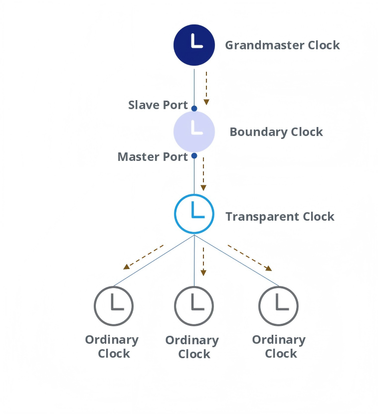
- PTP Domain: An independent “time synchronization circle.” Within a single domain, there is one and only one absolute Grandmaster clock source, and all devices in that domain must synchronize to it.
- PTP Port: A physical interface on a device running the PTP protocol. These ports hold three distinct identities:
- Master Port: The time publisher (only distributes time downwards).
- Slave Port: The time receiver (only accepts time from upstairs).
- Passive Port: Stays silent. It neither receives nor publishes time, strictly used to prevent “timing loops” in the network.
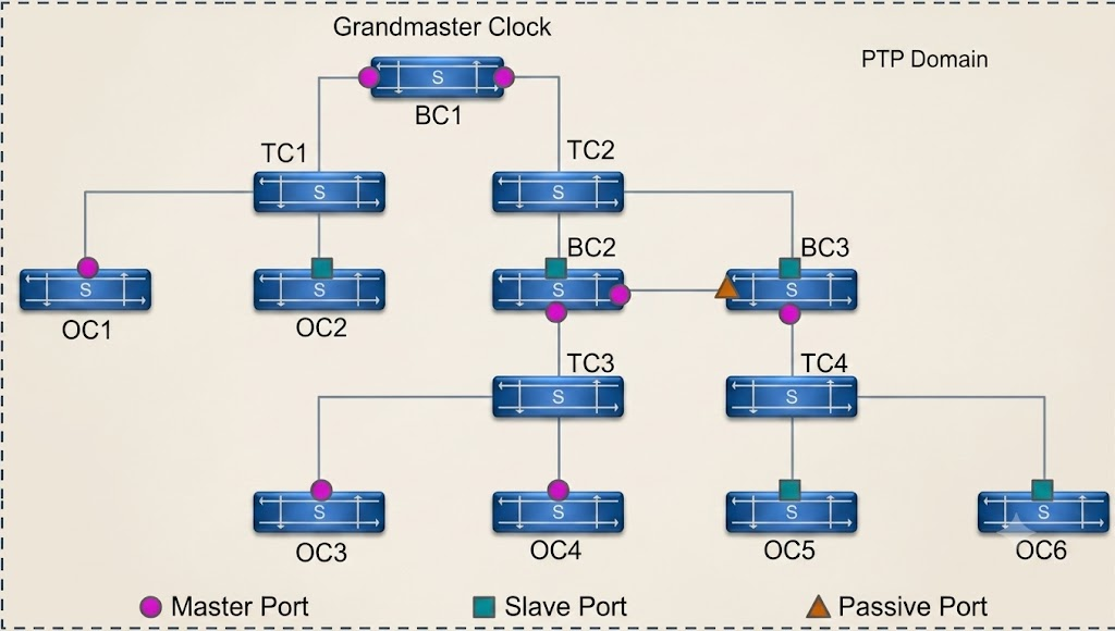
Three Clock Nodes: What Do Switches Actually Do Inside?
While ordinary switches just blindly forward PTP packets as regular data, a PTP-capable switch must actively participate by acting as one of the following three clock nodes:
- OC (Ordinary Clock)
Characteristics: Possesses only a single PTP port.
Role: It acts either as the absolute ultimate time source for the entire network (Grandmaster) or as a terminal device at the very edge of the network (e.g., servers, 5G base stations).
- BC (Boundary Clock)
Characteristics: Possesses multiple PTP ports.
Role: The “Middleman” of Time. Its upstream port acts as a Slave to align with the higher-level clock. Once synchronized, its downstream ports turn into Masters, generating completely fresh PTP messages to distribute to the lower tier. This segments the network into hops, isolating and blocking the accumulation of time errors.
- TC (Transparent Clock)
Characteristics: Possesses multiple PTP ports, but it never synchronizes its own clock with anyone else.
Role: The “Speed Radar” of Time. It behaves like a pane of transparent glass. As PTP packets pass through it, the switch precisely measures exactly how many nanoseconds the packet spent queuing and forwarding inside the switch (Residence Time). It then writes this error directly into the packet’s Correction Field. The downstream device receives it and simply subtracts this internal delay.
The Ultimate Boss: Grandmaster Clock (GM)
The Grandmaster Clock is the absolute soul of the entire PTP domain.
It does not look at anyone else’s clock. Its time is derived directly from the most absolute external physical sources: GPS, BeiDou satellite signals, or localized atomic clocks.
Through a strict hierarchical chain of command (Grandmaster Clock -> Boundary Clock / Transparent Clock -> Ordinary Clock), high-precision time flows seamlessly like water, expanding across every corner of the network without degradation.
In the PTP protocol, operations are primarily divided into two modes—E2E (End-to-End) and P2P (Peer-to-Peer)—depending on the network topology and how the transparent clocks resolve propagation delays.
Core Comparison: E2E (End-to-End) vs. P2P (Peer-to-Peer) Delay Measurement Models
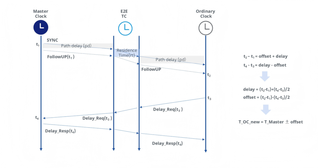
End-to-End (E2E) Delay Mechanism
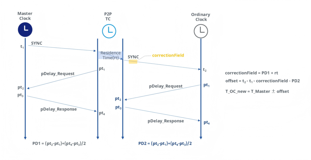
Peer-to-Peer (P2P) Delay Mechanism
| Feature | End-to-End Model (E2E) | Peer-to-Peer Model (P2P) |
| Mechanism | The Slave sends a Delay_Req directly to the Master, which replies with a Delay_Resp. Total latency is calculated end-to-end across the entire path. | Peer delay messages (pDelay_Req / pDelay_Resp) are continuously exchanged between each pair of directly connected neighbor nodes to measure link latency link-by-link. |
| Switch PTP Support | Optional. Allows non-PTP legacy switches in the network path, provided that intermediate TCs inject their Residence Time (RT) into the Correction Field (CF). | Mandatory. Every single switch along the network path must support PTP; it cannot traverse legacy non-PTP network switches. |
| Delay Compensation | Estimates total end-to-end path delay by combining bidirectional message timestamps with the RT corrected by intermediate TCs. | Correction Field (CF) = Uplink Link Delay (PD1) + Residence Time (RT). Offset = t2 – t1 – CF – Downlink Link Delay (PD2), achieving real-time, hop-by-hop compensation. |
| Synchronization Accuracy | Moderate. Vulnerable to asymmetric path jitter introduced by legacy network mixing; typically ranges from hundreds of nanoseconds to microseconds. | Ultra-High. Hardware-level alignment across the entire topology, consistently controlled within less than or equal to 100ns. |
| Application Profile | Typically used in hybrid or complex legacy/broadcasting environments (e.g., SMPTE ST 2059-2 for Media & Broadcast). | Typically used in topologies where all devices support PTP natively (e.g., IEEE 1588v2 / 5G O-RAN Fronthaul). |
3. What is the Difference Between PTP and NTP?
Many people easily confuse PTP with NTP because they are both protocols designed to “set the clock.” However, their synchronization accuracy and underlying execution logic differ by a factor of 1 million.
NTP (Network Time Protocol)
The bedrock of the internet. Your Windows PC, Linux servers, and smartphones all use it every day to stay aligned with standard world time.
- Accuracy: Millisecond-level ($$m$$, $$10^{-3$$ seconds).
- Pros: Extremely simple, zero hardware cost, runs effortlessly on any standard switch.
- Cons: Too coarse; completely incapable of handling industrial-grade, hard real-time tasks.
PTP (Precision Time Protocol)
A strict necessity for hard real-time networks. Born for extreme precision.
- Accuracy: Microsecond-level ($$\mu $$) or even nanosecond-level ($$n$$, $$10^{-9$$ seconds).
- Pros: Infuriatingly precise.
- Cons: Demands strict network hardware support (PHY/MAC chips) to execute hardware timestamping along the entire data path.
Core Metric Comparison Wall
| Dimension | NTP (Network Time Protocol) | PTP (Precision Time Protocol) |
| Ultimate Goal | Coarse-grained “wall-clock time” (Daily office work / General logging) | Ultra-precise “distributed coordination” (5G / Industrial control / Broadcasting) |
| Sync Accuracy | Millisecond-level | Microsecond / Nanosecond-level |
| Underlying Dependency | Software Sync (The CPU stamps packets only when it has free cycles) | Hardware Timestamping (Packets are stamped by hardware the moment they hit the port) |
| Hardware Requirement | Zero. Runs on any ordinary switch. | Hard Obligation. The entire network path must consist of PTP switches. |
| Typical Use Cases | Web browsing, daily office IT, standard server logs | 5G fronthaul networks, high-frequency trading, multi-camera frame sync,broadcasting |
4. What is the difference between PTP and network latency?
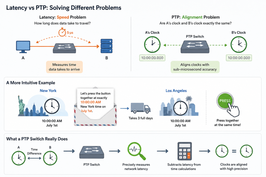
This is one of the most common misconceptions in the tech world: “If I buy a PTP-enabled switch, will my network latency become lower?” — not at all. They are completely unrelated.
• Latency: solves the speed problem. It measures how long it takes for data to travel from A to B (e.g., 5 microseconds).
• PTP: solves the alignment problem. It ensures whether A’s clock and B’s clock are exactly the same.
Here is a more intuitive example: a courier sends a letter from New York to Los Angeles, which takes 3 full days. That is high latency. But inside the letter it says: “Let’s press the button together at exactly 10:00:00 AM New York time on July 1st.” As long as the clocks in New York and Los Angeles are perfectly synchronized (guaranteed by PTP), they can still press the button simultaneously on July 1st, even though the message took 3 days to arrive.
A PTP switch is not designed to eliminate latency, but to precisely measure how much latency exists, and subtract it from time calculations.
Asterfusion SONiC-Based Open Network Switches Support Precision Time Protocol (PTP)
AsterNOS delivers an enterprise-grade, high-precision Precision Time Protocol (PTP) solution designed to meet the nanosecond-level timing accuracy required by modern distributed infrastructures. By coupling hardware-level timestamping with a decoupled software architecture, AsterNOS provides carrier-grade frequency and phase synchronization across diverse critical industries, including 5G O-RAN, financial high-frequency trading (HFT), and IP media broadcasting (SMPTE ST 2110).
Main Features
Unified Architecture & Full Clock Roles
AsterNOS provides seamless topological adaptability by natively supporting all IEEE 1588v2 clock identities:
- Grandmaster Clock (GM): Leverages an integrated GNSS receiver to serve as the absolute Stratum-1 reference time source for the entire clock domain.(CX306p-48S)
- Boundary Clock (BC): Terminates and regenerates PTP messages hop-by-hop, isolating upstream clock jitter and blocking error accumulation across large network topologies.
- Transparent Clock (TC): Computes packet Residence Time (RT) at the hardware layer and updates the Correction Field (CF) on the fly, completely eliminating packet delay variation (PDV) caused by network queuing.
- Ordinary Clock (OC): Functions as a high-precision edge synchronization terminal for servers, network interface cards (NICs), or base stations.
Multi-Profile Compliance & Multi-Instance PTP
Cross-Industry Profiles: Fully compliant with mainstream telecom, power, and media standards, including IEEE 1588v2, ITU-T G.8275.1/.2, and SMPTE ST 2059-2 / AES67.
Multi-Instance Operation: Supports concurrent execution of multiple PTP instances and distinct profiles on a single physical switch. This prevents domain conflicts and achieves physical isolation of clock planes in converged 5G fronthaul, industrial IoT, and broadcast networks.
Nanosecond Precision at Scale
Sub-20ns Accuracy: Delivers ultra-precise phase synchronization stable within , eliminating air-interface time slot collisions in 5G RAN and ensuring perfect lip-sync alignment in uncompressed 4K IP video streaming.
Massive Fan-Out Capacity: Supports up to 48 concurrent downstream slave clocks per device, radically lowering the Total Cost of Ownership (TCO) in massive-scale data center cluster deployments.
| Feature | Specification Details |
| Supported Clock Types | • Grandmaster Clock (with integrated GNSS receiver) • Boundary Clock (BC) • Transparent Clock (TC) • Ordinary Clock (OC) |
| PTP Profiles | • IEEE 1588v2 (Default Profile) • SMPTE ST 2059-2 (Media & Broadcast) • ITU-T G.8275.1 (Telecom Phase/Time – Full Network Support) • ITU-T G.8275.2 (Telecom Phase/Time – Partial Network Support/L3 Unicast) • AES67 (Audio-over-IP) |
| Timestamping Modes | • One-step (On-the-fly hardware timestamp insertion) • Two-step (Follow_Up message timestamp conveyance) |
| Delay Measurement Modes | • E2E (End-to-End) • P2P (Peer-to-Peer) |
| PTP Multi-Instance | Supported (Concurrent multi-domain and multi-profile isolation) |
| Synchronous Ethernet (SyncE) | Supported (Physical layer frequency synchronization) |
| Clock Selection Algorithm | Supported (Best Master Clock Algorithm – BMCA) |
Product | PTP Time Synchronization ITU Classification | Description |
Class A | Support different access rates and enabling flexible deployment across diverse application scenarios Optional PTP module supports SyncE | |
Class C |
In our next post, we will delve into PTP Time Synchronization and the ITU Classifications: Class A, Class B, and Class C.What Is PTP Time Synchronization?