

Preface
Because LLMs differ significantly from traditional cloud computing workloads, traditional data center networks are not well suited to LLM training scenarios. Traffic in LLM training is dominated by elephant flows, which makes ECMP algorithms prone to hash polarization and results in uneven traffic distribution; a dual-plane architecture effectively avoids this hash polarization problem. In addition, LLM training requires GPUs to complete iterative computations in synchronization, making it extremely sensitive to single points of failure. The dual-plane architecture uses a dual-uplink NIC design that provides strong fault tolerance, so that a single Leaf or link failure does not interrupt training.
This document focuses on the design of a dual-plane network for the GPU back-end of AI computing clusters. Using Asterfusion data center 400G/800G high-density-interface switches as the core hardware platform, it adopts a Clos network topology based on a Rail-optimized architecture to provide a standardized deployment solution.
Intended Audience
This manual is intended primarily for solution planning and design personnel and on-site implementation engineers, who should have the following capabilities:
- Familiarity with Asterfusion data center network switch products
- An understanding of technologies such as EVPN Multi-Homing and RoCE
Revision History
| Date | Version | Change Description |
| 2026-4-29 | V1.0 | Initial release |
1 Overview
With the rapid development of artificial intelligence technology, large language model (LLM) training has become a new challenge facing data center networks. Compared with traditional cloud computing applications, LLM training exhibits significantly different traffic characteristics and technical requirements:
Evolution and Challenges of AI Computing Networks
- Explosive scale growth: GPU cluster sizes are growing exponentially, from thousands to tens of thousands of GPUs and beyond
- Traffic pattern shift: Elephant flows dominated by collective communication operations such as All-Reduce and All-Gather have become the primary traffic characteristic
- Extreme performance requirements: Nanosecond-level latency, zero packet loss, and high throughput are hard requirements for AI training
- Sharply increased reliability pressure: A single point of failure can waste tens of thousands of GPUs’ worth of compute resources and interrupt training jobs
The convergent design of traditional data center networks tends to cause congestion and packet loss under high-density AI traffic, severely impacting training efficiency. A dual-plane architecture effectively addresses these challenges:
- Avoiding hash polarization: Physically isolated, independent forwarding planes fundamentally eliminate ECMP hash collisions
- Improving fault tolerance: A dual-uplink NIC design ensures that a single Leaf or link failure does not interrupt training
- Ensuring training continuity: LLM training requires GPUs to complete iterative computations in synchronization, making it extremely sensitive to single points of failure; the dual-plane architecture provides inherent redundant protection
2 AI Computing Dual-Plane Network Architecture
2.1 Rail-Only and Rail-Optimized Architectures
The Leaf nodes connected to same-numbered GPUs across different servers are defined as a Rail plane—that is, Rail N interconnects all GPU N ports through the Nth Leaf switch. As shown in the figure below, the GPUs on each server are numbered 0–7, corresponding to Rail 1 through Rail 8. Same-rail transmission refers to a case where the NICs corresponding to the source and destination GPUs connect to the same Leaf switch. LLM (Large Language Model) training uses hybrid parallelism strategies (data parallelism, tensor parallelism, and pipeline parallelism) to optimize traffic distribution, concentrating most traffic within a node and within the same rail.
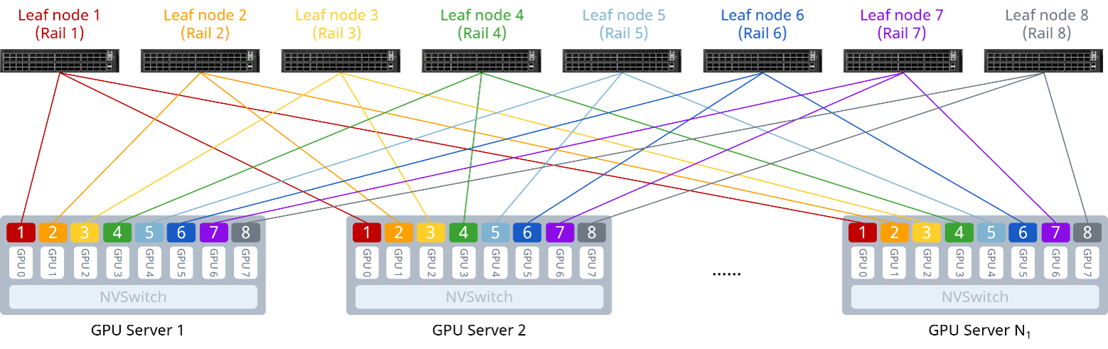
The Rail-only architecture uses a single-tier network design that physically divides the entire cluster network into 8 independent rails. Communication between GPUs on different nodes always occurs over the same rail, allowing intra-rail communication to be completed in a single hop.
Building on the Rail concept, a basic building block composed of a group of Rails—containing a number of Leaf switches and GPU servers—is referred to as a Group. As the cluster scales up, additional Groups can be stacked horizontally to support larger cluster deployments.
The compute network can be thought of as a railway system: compute nodes are the “stations” that carry compute power; a Rail is the “dedicated railway line” connecting the same-numbered GPU at each station, ensuring high-speed direct transit; and a Group is the “standard platform zone” unit that integrates multiple rails and their associated switches. Through this modular stacking approach, an AI computing center can scale out like building blocks—ensuring extremely fast communication within a single rail while achieving efficient interconnection across clusters of tens of thousands of GPUs.
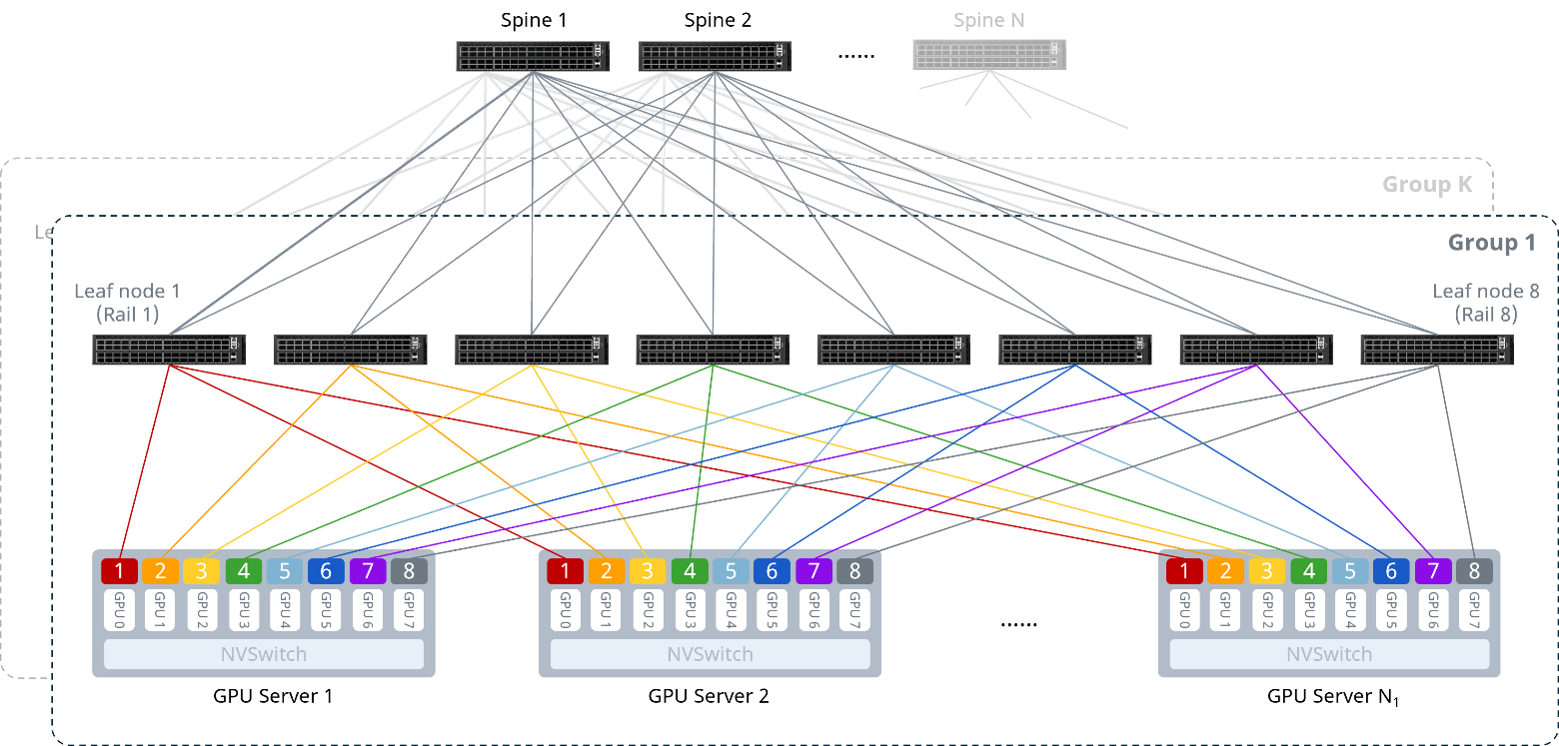
As shown in the figure above, the core design principle of the Rail-optimized architecture is to connect the same-numbered NIC on every server to the same Leaf switch, ensuring that multi-machine GPU-to-GPU communication completes in as few hops as possible. Under this design, communication between GPU nodes can use the internal NVSwitch[] pathway, reaching its destination in a single hop without traversing multiple switches, thereby avoiding additional latency. Specifically[1]
① Intra-server interconnection: 8 GPUs are connected to the NVSwitch via the NVLink bus, enabling low-latency GPU-to-GPU communication within the server and reducing pressure on the Scale-Out network;
② Server-to-network interconnection: All servers follow a unified cabling scheme, with NICs connected to multiple Leaf switches according to the rule “NIC1–Leaf1, NIC2–Leaf2…”;
③ Network-layer interconnection: The Leaf and Spine switches are fully meshed, forming a two-tier Clos architecture.
2.2 Dual-Plane Architecture
The dual plane is an innovative network architecture that optimizes the interconnection of large-scale GPU clusters by building two identical network planes. Each GPU corresponds to two NIC ports, with each port connected to a different network plane, as shown in Figure 3. The two network planes have identical topologies and have no cross-connections whatsoever. This design substantially reduces the probability of hash polarization and optimizes communication efficiency. The dual-plane architecture not only improves network performance but also enhances network stability and reliability—even if a single device or a single plane experiences a network failure, the normal operation of the entire cluster network is not affected.
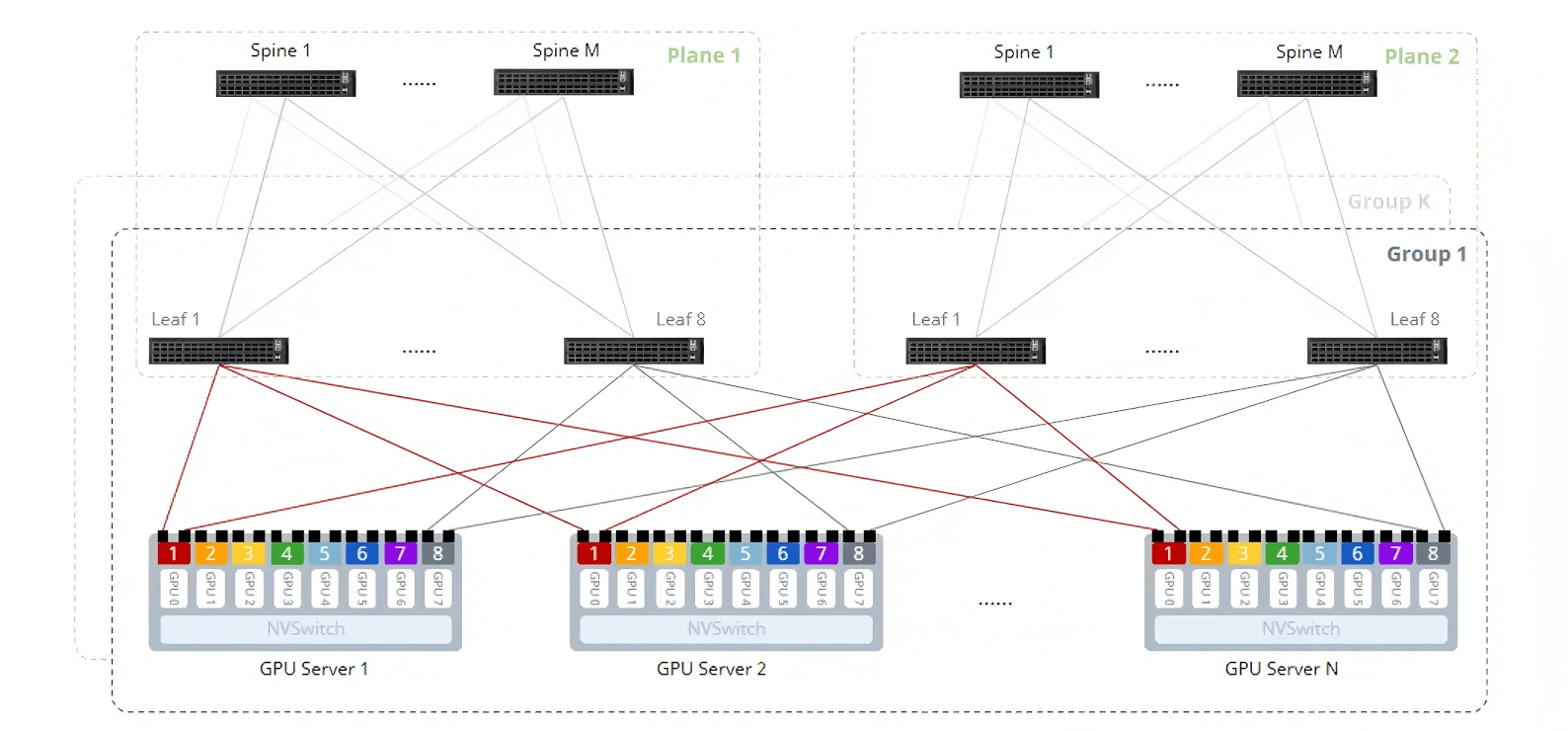
The dual-plane architecture divides the network into two fully independent forwarding planes (Plane 1 and Plane 2), each containing a complete Clos architecture hierarchy. The two planes are physically fully isolated from each other, ensuring the independence of each forwarding plane and fault isolation.
| Comparison Dimension | Traditional Single-Plane Architecture | Dual-Plane Architecture |
| Hash collisions | Severe hash polarization | Natural traffic splitting, evenly distributed traffic |
| Fault impact | Network-wide impact | Plane-level isolation |
| Scalability | Limited linear scaling | Plane-level scaling supports larger scale |
| Determinism | Variable paths, poor determinism | Fixed paths, predictable performance |
3 Technologies Supporting the Dual-Plane Network
3.1 Dual-Plane Technology
In a dual-plane network architecture, each NIC must present two ports connected simultaneously to two Leaf switches, producing an effect similar to a dual-uplink Leaf stack. In traditional data center networks, MC-LAG (Multi-Chassis Link Aggregation Group) is commonly used to implement a stacked dual-Leaf architecture. In a stacked dual-Leaf architecture, the two Leaf switches are connected by a direct link, which is essential for synchronizing data-plane forwarding information such as ARP and MAC entries. This approach significantly reduces the system performance degradation caused by an individual Leaf switch failure in production environments; however, because the direct link between the two Leaf switches must also carry service traffic during a failure, it consumes a large amount of switch bandwidth. The dual-plane network solution offers two selectable approaches for implementing a dual-Leaf architecture: one relies on the NIC’s dual ARP transmission capability, and the other relies on the switch’s EVPN MH (EVPN Multi-Homing) capability.
3.1.1 Dual-Uplink Leaf with Dual NIC Transmission
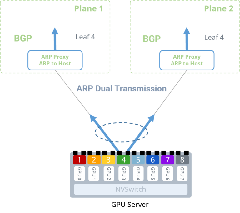
The core of this implementation is to remove the physical direct link between the two Leaf switches, and instead achieve a stacking-like high-availability effect through coordination between the end-host NIC and the switches. In this implementation, the server NIC uses bond mode with dual uplinks, connecting separately to the Leaf switches on the two planes. The two Leaf switches are not physically stacked and have no dedicated direct synchronization link.
The key technical challenge is ensuring that, without a direct link, the two Leaf switches maintain consistent ARP requests and MAC address learning for the server, thereby enabling seamless traffic switchover. This is achieved mainly through the following aspects:
Dual ARP transmission from the NIC: This is the core dependency of the solution. The server NIC must be able to send ARP requests simultaneously on both uplink ports. This allows both Leaf switches to learn the server’s MAC address and IP address.
Switch ARP proxy and ARP-to-host-route conversion: The Leaf switch enables ARP proxy and converts the learned ARP entries into 32-bit host routes (ARP-to-Host Route), which are advertised to the entire plane via the upstream BGP protocol.
In this way, the switches on both network planes can obtain complete host routes for the server NICs.
3.1.2 Dual-Uplink Leaf with EVPN MH
EVPN MH is a multi-homed, active-active VXLAN gateway solution defined in RFC 7432, using BGP EVPN as the control plane. Similar to the MC-LAG approach, EVPN MH provides highly reliable support for access scenarios, delivering load balancing and fault tolerance. Compared with the existing MC-LAG approach, EVPN MH is implemented according to the RFC standard and offers good compatibility. It also eliminates the need to deploy physical cabling between active-active devices, making it easier to scale.
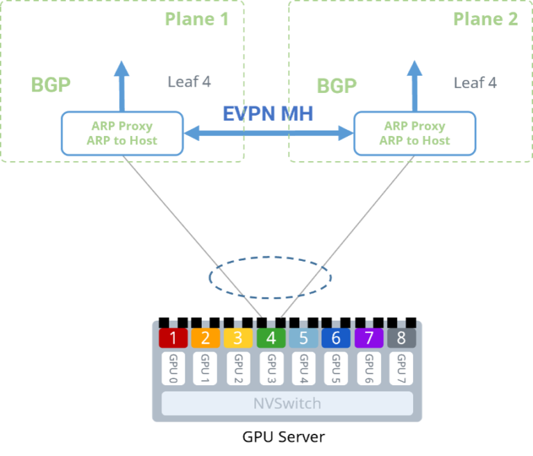
In this implementation, the two Leaf switches act as EVPN PE devices and establish a BGP-EVPN protocol connection directly over the management network or the switch’s AUX 10G link (a non-service port), jointly serving the same group of GPU servers. The core mechanism uses an ESI (Ethernet Segment Identifier) to identify the two physical links to which the server is connected, thereby enabling multi-homed access to the same Ethernet segment.
The working principle is illustrated below: after the server NIC’s ARP broadcast is load-balanced by the bond, it is sent to the Leaf device on one of the planes. That Leaf device floods the ARP broadcast into the VXLAN tunnel, allowing the Leaf at the other end of the tunnel (on the different plane) to synchronously learn the ARP entry. The two Leaf switches on different planes then convert the learned ARP entries into 32-bit host routes (ARP-to-Host Route), which are advertised to the entire plane via the upstream BGP protocol.
3.2 Load-Balancing Technologies
ECMP (Equal-Cost Multi-Path) per-flow load balancing is the most widely used path-selection strategy in data center networks. It uses fixed packet fields (such as source/destination MAC addresses and the IP 5-tuple) as hash factors, applying a hash algorithm to generate a hash value that is used to select a path pseudo-randomly among multiple available paths. This load-balancing method, based on packet header fields, is also known as static load balancing.
However, per-flow load balancing is prone to uneven load distribution when traffic characteristics are homogeneous, and especially when “elephant flows” occur, congestion on the selected member link can be exacerbated, severely impacting network performance and even causing packet loss. Deep learning models rely heavily on collective communication operations such as All-Reduce, All-Gather, and Broadcast, which generate intense traffic interaction among GPUs, often at transmission rates of several terabits per second (Tbps). At the same time, the collective communication that large-model parameter synchronization depends on suffers from a bottleneck effect—if traffic distribution is uneven, congestion on even a single path can slow down the entire training job and amplify the negative impact. For this reason, traditional per-flow load balancing is not well suited to AI computing networks.
To address this issue, this document introduces three technical approaches that replace traditional per-flow load balancing: Flowlet-based load balancing, intelligent path selection, and packet spraying.
3.2.1 Adaptive Routing and Switching
ARS (Adaptive Routing and Switching) is a Flowlet-based load-balancing technology. Leveraging the hardware ALB (Auto-Load-Balancing)[2] capability provided by the ASIC, it achieves a load balance close to per-packet distribution while reducing packet reordering. This technology splits flows with the same hash value into a series of Flowlets at defined time intervals, then actively distributes each Flowlet to an idle path based on real-time awareness of link-quality indicators such as port bandwidth utilization and queue depth, thereby improving overall network bandwidth utilization.
3.2.2 Intelligent Path Selection
Dynamic intelligent path selection is a load-balancing technology based on path awareness that comprehensively evaluates key parameters such as bandwidth usage, queue occupancy, and forwarding latency to precisely assess network path quality. Bandwidth and queue usage are measured via ASIC hardware register statistics with sub-100-millisecond precision, while forwarding latency is measured using INT (In-band Network Telemetry) with nanosecond-level precision. Each switch monitors path quality in real time, propagates this information via BGP extended attributes, and combines it with per-flow dynamic WCMP (Weighted Cost Multipath) to dynamically distribute traffic to the optimal path, avoiding network bottlenecks and improving bandwidth utilization.
Static intelligent path selection is a load-balancing technology based on preset policies. Traffic from GPUs destined for different downlink interfaces on the Leaf is isolated and directionally forwarded, and PBR (Policy-Based Routing) is used to redirect traffic to a specified Leaf uplink interface, routing it to a preset Spine device to achieve uplink load balancing under a 1:1 convergence ratio. This technology strongly binds specific traffic to a physical path, making it suitable for scenarios that require high path stability and have relatively fixed traffic patterns.
3.2.3 Packet Spraying
Packet spraying[2] is a per-packet load-balancing technology that evenly sprays packets across all links to avoid congestion on any single path. Packet spraying includes two algorithms:
• Random algorithm: Randomly distributes packets across the links;
• Round Robin algorithm: Distributes packets to the links one by one, in sequence and in equal amounts.
Although per-packet load balancing can theoretically maximize network utilization, it also faces a significant challenge: in actual network deployments, when packets reach their destination via different links, differences in per-link forwarding latency cause packets to arrive out of order at the receiving end, impacting overall performance. As a result, per-packet load balancing requires strong hardware-level support—specifically, high-performance NICs on the end hosts must be capable of packet reordering.
4 Building a 400G AI Computing Dual-Plane Network
4.1 Building a 400G AI Computing Dual-Plane Network
4.1.1 Network Topology Solution
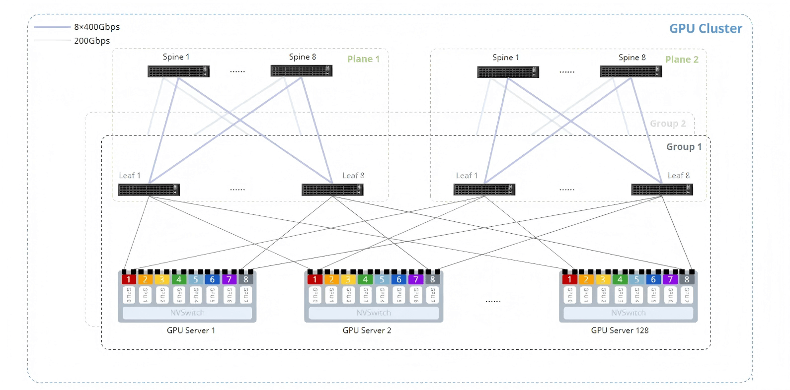
The figure above shows a 400G AI computing dual-plane Rail-optimized network topology for 256 compute nodes (2,048 GPUs), deploying 48 CX864E-N switches (16 Spine nodes and 32 Leaf nodes), consisting of two planes, each with 16 Leaf nodes and 8 Spine nodes. The core design principles are as follows:
- Each GPU connects to a dedicated 400G NIC, and each 400G NIC has two ports that connect to the two separate planes. The first port on each server’s NIC connects to a Leaf switch on Plane 1 according to the rule “NIC1–Leaf1, NIC2–Leaf2…”, and the second port on each server’s NIC connects to a Leaf switch on Plane 2 according to the same rule;
- Each plane network uses a two-tier Clos architecture, with Spine and Leaf switches fully meshed within the plane. IPv6 link-local addressing is used to establish unnumbered BGP neighbor relationships that advertise the subnet routes for each Rail, achieving route exchange without the need to plan IP addresses for the Leaf-Spine interconnect interfaces;
- The ratio of Leaf downlink to uplink capacity must strictly follow a 1:1 convergence ratio to guarantee non-blocking transmission;
- The Leaf and Spine switches enable one-click RoCE and load-balancing features to build a lossless network.
4.1.2 Device Selection
For building medium-to-large-scale 400 Gbps RoCEv2 networks, it is recommended to use the data center switches CX864E-N and CX732Q-N, leveraging their ultra-low forwarding latency: the CX864E-N offers end-to-end forwarding latency as low as 560 ns, and the CX732Q-N as low as 500 ns, enabling same-rail transmission latency of approximately 600 ns. End-to-end network latency for cross-rail (Leaf-Spine-Leaf) Layer 3 forwarding is kept within 2 µs, fully meeting the stringent low-latency requirements of RoCEv2 networks.
In a dual-plane Rail-optimized network, the number of Leaf nodes within a single Group is related to the number of GPUs per server (i.e., the number of Rails). Taking the NVIDIA DGX H100 GPU server (with 8 GPUs per server) as an example, a Group requires 16 Leaf nodes, corresponding to 8 Rails.
The maximum number of servers that can connect to a Group is related to the interface configuration of the Leaf nodes. To maintain a 1:1 convergence ratio, half of each Leaf node’s interfaces are used to connect GPU servers and the other half connect to Spine nodes; therefore, the maximum number of GPU servers that can connect to a Group is half the number of available interfaces on the Leaf nodes.
The tables below show the node configuration requirements for deploying dual-plane networks with different GPU counts using the CX864E-N and CX732Q-N, respectively:
| Total GPUs / Servers | Number of Leaf Nodes | Number of Spine Nodes | 400G Links per Leaf-Spine Pair |
| 512/64 | 8 | 4 | 32 |
| 1024/128 | 16 | 8 | 16 |
| 2048/256 | 32 | 16 | 8 |
| 4096/512 | 64 | 32 | 4 |
| 8192/1024 | 128 | 64 | 2 |
| 16384/2048 | 256 | 128 | 1 |
| Total GPUs / Servers | Number of Leaf Nodes | Number of Spine Nodes | 400G Links per Leaf-Spine Pair |
| 256/32 | 16 | 8 | 4 |
| 512/64 | 32 | 16 | 2 |
| 1024/128 | 64 | 32 | 1 |
5 Conclusion
With the rapid advancement of artificial intelligence technology, AI computing networks are undergoing unprecedented transformation. This solution provides a systematic explanation of the design philosophy and technical implementation of AI computing networks based on a dual-plane architecture, offering a complete solution for building networks for large-scale GPU clusters. This solution can effectively support dual-plane compute network deployments for AI clusters of varying scales. For specific configuration and implementation examples, please refer to the related best practices document.
[1] NVSwitch is a switching chip introduced by NVIDIA that carries high-speed NVLink traffic, enabling multiple GPUs in a Scale-Up network to communicate at the maximum speed achievable over NVLink.
[2] The CX864E-N model supports this capability.