

Preface
This document provides a detailed introduction to the Underlay high-reliability access solution based on ARP-to-host-route conversion for data center switches in a Leaf-Spine architecture, along with the corresponding deployment baseline, configuration methods, and operations and maintenance guidance.
Intended Audience
This manual is intended primarily for solution planning and design personnel and on-site implementation engineers, who should have the following capabilities:
- Familiarity with Asterfusion data center network switch products
- An understanding of the basic principles of ARP-to-host-route conversion technology
Revision History
| Date | Version | Change Description |
| 2026-05-11 | V1.0 | Initial release |
| 2026-06-17 | V1.1 | Updated |
1 Overview
In a pure Underlay network architecture that does not introduce an Overlay control plane (such as EVPN), “ARP-to-host-route conversion” technology can be used to achieve highly reliable forwarding at the access layer. This solution converts host ARP entries in the data plane into /32 host routes and, combined with a multipath forwarding mechanism, improves the network’s fault tolerance and convergence performance.
1.1 Technical Principles
ECMP Forwarding Based on Host Routes
By establishing multiple /32 host routes for the same host, each pointing to a different next-hop device, the system can achieve ECMP (Equal-Cost Multi-Path) forwarding at host granularity. Compared with traditional subnet-based load-sharing methods, this mechanism offers higher forwarding precision and path utilization.
Fast Fault Convergence
When a link or device fails, the corresponding next hop becomes invalid, and the device can quickly remove the failed path from the associated host route, retaining only the reachable paths to continue forwarding traffic. This process does not depend on gateway switchover, which significantly shortens convergence time and reduces the impact of service interruption. Data forwarding can select paths directly based on the destination host route, reducing dependency on a single gateway node and thereby improving the overall reliability of the network.
1.2 Solution Features and Applicability
Advantages:
- No need to introduce an Overlay control protocol, resulting in a simple architecture and low deployment complexity
- Supports ECMP-based multipath forwarding, achieving link-level high reliability
- Forwarding decisions are made based on host-level (/32) routes, allowing traffic from different hosts to be distributed across different paths, which improves link utilization
Limitations:
- Host information relies on ARP learning and routing table entry learning. The lack of a centralized control plane for unified distribution and management results in weaker cross-device state consistency, and also limits capabilities in policy orchestration (such as isolation control, security policies, and routing policies) and traffic path scheduling
- In dual-homed scenarios, this approach relies on the server having ARP dual-transmission or equivalent capability
- In large-scale networks, ARP broadcasts may create scalability pressure, requiring the use of ARP suppression mechanisms
The ARP-to-host-route conversion solution converts data-plane learning results into host-level routes, providing multipath forwarding and fast convergence capability in a pure Underlay network. It can meet the high-reliability access requirements of small- to medium-sized data centers or scenarios that prioritize architectural simplicity. For large-scale networks or those requiring higher control precision, combine this solution with an Overlay control plane to further enhance network capabilities.
1.3 Network Topology Solution
The Underlay high-reliability access network topology solution based on ARP-to-host-route conversion is shown in Figure 1-1.
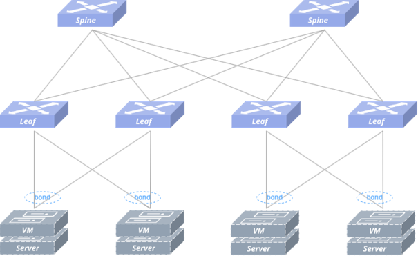
Figure 1-1 Typical Network Topology of the Underlay High-Reliability Access Solution Based on ARP-to-Host-Route Conversion
Note: Service servers use bond interfaces to connect to the Server Leaf switches via dual uplinks. The Spine and Leaf switches are interconnected and run a routing protocol to achieve IP Layer 3 network connectivity.
The table below shows the recommended deployment method for this solution.
Table 1-1 Recommended Deployment Method
| Description | Recommended Deployment Method |
| Leaf-Spine Interconnection | – Routing protocol selection: BGP is the most commonly used routing protocol in data center Spine-Leaf architectures. It is recommended to use BGP to achieve Layer 3 interconnection and route reachability for the Underlay network. – Neighbor establishment recommendation: It is recommended to establish BGP Unnumbered neighbor relationships based on IPv6 link-local addresses. This approach eliminates the need for IP address planning on interconnect links, effectively reducing configuration complexity and simplifying network deployment and operations. – AS planning recommendation: It is recommended that Spine-layer devices use the same Autonomous System (AS) number, while Leaf-layer devices use different AS numbers, to reduce path redundancy and path-selection computation overhead, thereby lowering routing table entry consumption and improving network convergence stability. It is recommended that Leaf-layer switches use different AS numbers; if the same AS number is used, the allowas-in feature must be configured on the Leaf switches. – Link deployment method: It is recommended to interconnect the Leaf and Spine switches using high-speed interfaces. The interfaces can be configured directly as physical Layer 3 ports, or, depending on bandwidth requirements, combined into a Link Aggregation Group (LAG) to increase the bandwidth and reliability of the interconnect link. |
| Connecting Servers/Switches to Leaf Devices | – It is recommended to interconnect the Leaf switch and the access device using low-speed interfaces, which support configuring multiple aggregation members; – To improve system reliability, it is recommended to configure LACP dynamic aggregation and enable LACP fast-rate (short timeout) to improve fault convergence performance. – It is recommended that the server side use bond4 (load-sharing) mode for bonding;[1] – In scenarios where a server is deployed and installed via PXE, the LACP fallback feature must be enabled on the aggregation interface of the Leaf switch to which it is connected. |
| Deploying the Leaf Layer 3 Active-Active Gateway | – A pair of Leaf devices acting as the Layer 3 gateway should present the same IP and MAC address to the access side, meaning the same IP and MAC address should be configured on the gateway VLAN. In addition, each service VLAN supports the configuration of only one gateway IP address. |
| Load Sharing | – In a data center network, the BGP AS numbers of different nodes are typically different, so the AS-path of the routes learned by a device also differs. Therefore, the multipath feature needs to be enabled on the nodes that receive the routes (such as Spine, Leaf, and ToR) to achieve load sharing for services. |
| Configuring Fault Convergence Assurance | – It is recommended to configure a monitor link group (interface linkage group) on the Leaf devices to ensure fast convergence in the event of an uplink failure or device restart; – It is recommended to configure BGP graceful-restart (GR)[2] and BGP max-med on-startup[3] on the Leaf and Spine devices as needed, to ensure fast routing protocol convergence in the event of a node-level failure. |
[1] There are currently seven server NIC bonding modes in total (bond0 ~ 6), of which bond0, 1, and 4 are the most commonly used. Bond0 is load-balancing (round-robin) mode, which requires static aggregation to be configured on the switch; Bond1 is active-backup mode, which requires no configuration on the switch other than assigning the corresponding VLAN; Bond4 is LACP mode, which requires dynamic aggregation to be configured on the switch. In this solution, it is recommended that the server side use Bond4 mode for access.
[2] The BGP Graceful Restart capability defined in RFC 4724 defines a mechanism that allows a BGP speaker to continue forwarding packets along known routes while recovering routing protocol information. This feature helps reduce route flapping and unnecessary changes to the forwarding table, thereby improving network stability.
[3]BGP max-med on-startup is a feature that advertises routes with the maximum MED attribute value when a BGP session starts. This feature allows other switches to preferentially select routes from other BGP sessions for forwarding while a BGP session is restarting and recovering, reducing packet loss in traffic switchback scenarios.
2 Typical Configuration Example
2.1 Network Topology
The network topology is shown in Figure 2-1. The service servers connect to the Server Leaf switches via dual uplinks.
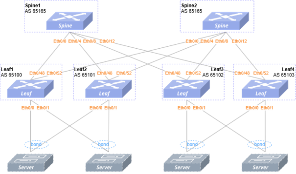
Figure 2-1 Network Topology of the Underlay High-Reliability Access Solution Based on ARP-to-Host-Route Conversion
Table 2-1 Interface IP Address Planning Table
| Device Name | Interface | IP Address | Device Name | Interface | IP Address |
| Spine1 | Loopback 0 | 172.16.1.165/32 | Spine2 | Loopback 0 | 172.16.1.167/32 |
| Leaf1 | Loopback 0 | 172.16.1.179/32 | Leaf2 | Loopback 0 | 172.16.1.166/32 |
| Vlan10 | 10.10.0.1/24 | Vlan10 | 10.10.0.1/24 | ||
| Vlan20 | 10.20.0.1/24 | Vlan20 | 10.20.0.1/24 | ||
| Leaf3 | Loopback 0 | 172.16.1.170/32 | Leaf4 | Loopback 0 | 172.16.1.162/32 |
| Vlan10 | 20.10.0.1/24 | Vlan10 | 20.10.0.1/24 | ||
| Vlan20 | 20.20.0.1/24 | Vlan20 | 20.20.0.1/24 |
2.2 Configuration Overview
The configuration baseline in this document covers only the Spine-Leaf network devices shown in Figure 2-1; configuration of other network devices is omitted.‑
Table 2-2 Configuration Overview
| Device Type to Be Deployed | Configuration Steps |
| Configuring the Spine Switch | Configuring interconnect interface and loopback interface IP addresses |
| Configuring the routing protocol for Layer 3 connectivity | |
| Configuring the Leaf Switch | Configuring interconnect interface and loopback interface IP addresses |
| Configuring the routing protocol for Layer 3 connectivity | |
| Configuring the VLAN Layer 3 gateway | |
| Configuring | |
| Configuring the downlink cross-device aggregation group | |
| Configuring the interface linkage group |
For the interface IP address table, see Table 2-1. The specific configuration steps are described below, using Leaf1, Leaf2, Spine1, and Spine2 as examples.
2.3 Configuring the Spine Switch
2.3.1 Configuring Interconnect Interface and Loopback Interface IP Addresses
Table 2-3 Configuring Interconnect Interface and Loopback Interface IP Addresses on the Spine
| Step Description | Spine1 | Spine2 |
| Enable the IPv6 use-link-local feature on the interfaces interconnected with the Leaf switches. | interface ethernet 0/0 description to_Leaf1 ipv6 use-link-local ! interface ethernet 0/4 description to_Leaf2 ipv6 use-link-local ! | interface ethernet 0/0 description to_Leaf1 ipv6 use-link-local ! interface ethernet 0/4 description to_Leaf2 ipv6 use-link-local ! |
| Configure the Loopback 0 IP address to serve as the Router ID. | interface loopback 0 ip address 172.16.1.165/32 ! | interface loopback 0 ip address 172.16.1.167/32 ! |
2.3.2 Configuring the Routing Protocol for Layer 3 Connectivity
Layer 3 connectivity between the Leaf and Spine switches is achieved by configuring the eBGP routing protocol on the interconnected physical interfaces.
Create a BGP peer group named PEER_to_Leaf on the Spine device to establish eBGP with the Leaf devices and advertise the service VLAN subnet routes.
Table 2-4 Configuring BGP Neighbors on the Spine
| Step Description | Spine1 | Spin2 |
| Configure the BGP AS number and Router ID, and enable the BGP max-med, multipath, and graceful-restart features. | router bgp 65165 bgp router-id 172.16.1.165 no bgp ebgp-requires-policy bgp bestpath as-path multipath-relax bgp max-med on-startup 120 bgp graceful-restart exit | router bgp 65165 bgp router-id 172.16.1.167 no bgp ebgp-requires-policy bgp bestpath as-path multipath-relax bgp max-med on-startup 120 bgp graceful-restart exit |
| Create the PEER_to_Leaf peer group and enable BFD. | neighbor PEER_to_Leaf peer-group neighbor PEER_to_Leaf remote-as external neighbor PEER_to_Leaf bfd neighbor ethernet 0/0 interface peer-group PEER_to_Leaf neighbor ethernet 0/4 interface peer-group PEER_to_Leaf neighbor ethernet 0/8 interface peer-group PEER_to_Leaf neighbor ethernet 0/12 interface peer-group PEER_to_Leaf ! | neighbor PEER_to_Leaf peer-group neighbor PEER_to_Leaf remote-as external neighbor PEER_to_Leaf bfd neighbor ethernet 0/0 interface peer-group PEER_to_Leaf neighbor ethernet 0/4 interface peer-group PEER_to_Leaf neighbor ethernet 0/8 interface peer-group PEER_to_Leaf neighbor ethernet 0/12 interface peer-group PEER_to_Leaf ! |
2.4 Configuring the Leaf Switch
2.4.1 Configuring Interconnect Interface and Loopback Interface IP Addresses
Table 2-5 Configuring Interconnect Interface and Loopback Interface IP Addresses on the Leaf
| Step Description | Leaf1 | Leaf2 |
| Enable the IPv6 use-link-local feature on the interfaces interconnected with the Spine switches. | interface ethernet 0/48 description to_Spine1 ipv6 use-link-local ! interface ethernet 0/52 description to_Spine2 ipv6 use-link-local ! | interface ethernet 0/48 description to_Spine1 ipv6 use-link-local ! interface ethernet 0/52 description to_Spine2 ipv6 use-link-local ! |
| Configure the Loopback 0 IP address to serve as the Router ID. | interface loopback 0 ip address 172.16.2.179/32 ! | interface loopback 0 ip address 172.16.1.166/32 ! |
2.4.2 Configuring the Routing Protocol for Layer 3 Connectivity
Layer 3 connectivity between the Leaf and Spine switches is achieved by configuring the eBGP routing protocol on the interconnected physical interfaces.
Create a BGP peer group named PEER_to_Spine on the Leaf device to establish eBGP with the Spine devices and advertise the service VLAN subnet routes. After the ARP-to-host-route conversion feature is enabled, ARP entries are automatically converted into kernel routes with a metric of 5200.
Table 2-6 Configuring BGP Neighbors on the Leaf
| Step Description | Leaf1 | Leaf2 |
| Create a route policy to filter ARP-to-host routes. | route-map filter permit 10 match metric 5200 exit ! | route-map filter permit 10 match metric 5200 exit ! |
| Configure BGP and the router ID, and enable the BGP GR, max-med, and multipath features. | router bgp 65100 bgp router-id 172.16.1.179 no bgp ebgp-requires-policy bgp bestpath as-path multipath-relax bgp max-med on-startup 120 bgp graceful-restart exit | router bgp 65101 bgp router-id 172.16.1.166 no bgp ebgp-requires-policy bgp bestpath as-path multipath-relax bgp max-med on-startup 120 bgp graceful-restart exit |
| Create the BGP peer group PEER_to_Spine and enable BFD. | neighbor PEER_to_Spine peer-group neighbor PEER_to_Spine remote-as external neighbor PEER_to_Spine bfd neighbor ethernet 0/48 interface peer-group PEER_to_Spine neighbor ethernet 0/52 interface peer-group PEER_to_Spine ! | neighbor PEER_to_Spine peer-group neighbor PEER_to_Spine remote-as external neighbor PEER_to_Spine bfd neighbor ethernet 0/48 interface peer-group PEER_to_Spine neighbor ethernet 0/52 interface peer-group PEER_to_Spine ! |
| Advertise the host routes converted from ARP. | address-family ipv4 unicast redistribute kernel route-map filter exit-address-family ! | address-family ipv4 unicast redistribute kernel route-map filter exit-address-family ! |
After completing the above configuration, you can check the BGP neighbor status using the show ip bgp summary command:
leaf-1# show ip bgp summary

IPv4 Unicast Summary (VRF default):
BGP router identifier 172.16.1.179, local AS number 65100 vrf-id 0
BGP table version 26
RIB entries 13, using 2392 bytes of memory
Peers 2, using 1447 KiB of memory
Peer groups 1, using 64 bytes of memory

Neighbor        V         AS   MsgRcvd   MsgSent   TblVer  InQ OutQ  Up/Down State/PfxRcd   PfxSnt Desc
ethernet 0/48  4      65165       135       135        0    0    0 02:00:22            4        7        N/A
ethernet 0/52  4      65165       133       135        0    0    0 02:00:11            4        7        N/A

Total number of neighbors 2
In the output, there are two key pieces of information to focus on:
- The State/PfxRcd column shows the current status of the BGP session: if it displays a state such as Idle/Connect/Active, this indicates an abnormality in BGP session establishment; if it displays a number, this indicates the BGP session was established successfully, and the number represents the count of route prefixes received from the BGP peer;
- Up/Down indicates the duration for which the BGP session has been in its current state.
2.4.3 Configuring the VLAN Layer 3 Gateway
Table 2-7 Configuring the VLAN Layer 3 Gateway‑Table 2-7 Configuring the VLAN Layer 3 Gateway
| Step Description | Leaf1 | Leaf2 |
| Create the VLAN. | vlan 10 exit vlan 20 exit | vlan 10 exit vlan 20 exit |
| Disable ARP broadcast flooding. | arp broadcast disable[4] | arp broadcast disable |
| Configure the Layer 3 gateway. The IP and MAC address of the same VLAN interface must be identical on the pair of Leaf devices, and ARP proxy must be enabled. | interface vlan 10 mac-address 00:00:00:10:00:00 ip address 10.10.0.1/24 arp proxy mode default exit interface vlan 20 mac-address 00:00:00:20:00:00 ip address 10.20.0.1/24 arp proxy mode default exit | interface vlan 10 mac-address 00:00:00:10:00:00 ip address 10.10.0.1/24 arp proxy mode default exit interface vlan 20 mac-address 00:00:00:20:00:00 ip address 10.20.0.1/24 arp proxy mode default exit |
[4] This command is supported only in version R0408P00 and later. If the switch indicates that this command is not supported, use the following commands instead:
policy-map type copp copp-system-policy
class copp-system-arp
trap-action trap
2.4.4 Configuring ARP-to-Host-Route Conversion
This product series provides a two-level conversion policy for ARP-to-host-route conversion:
- Level 1: Interface Policy
The available actions are permit/deny/pass. The user first configures the default interface policy, and can then configure a policy for a specific interface. If the receiving interface matches a specific interface, the specific policy is applied; otherwise, the default policy is applied. If the policy action is permit or deny, conversion is performed or not performed directly, without matching against the next-level subnet policy. If the policy action is pass, whether conversion is performed is determined by the next-level subnet policy;
- Level 2: Subnet Policy
The available actions are permit/deny. The user first configures the default subnet policy, and can then configure a policy for a specific subnet. If the neighbor IP matches a configured subnet, the specific policy is applied; otherwise, the default policy is applied.
2.4.4 Configuring ARP-to-Host-Route Conversion
This product series provides a two-level conversion policy for ARP-to-host-route conversion:
- Level 1: Interface Policy
The available actions are permit/deny/pass. The user first configures the default interface policy, and can then configure a policy for a specific interface. If the receiving interface matches a specific interface, the specific policy is applied; otherwise, the default policy is applied. If the policy action is permit or deny, conversion is performed or not performed directly, without matching against the next-level subnet policy. If the policy action is pass, whether conversion is performed is determined by the next-level subnet policy;
- Level 2: Subnet Policy
The available actions are permit/deny. The user first configures the default subnet policy, and can then configure a policy for a specific subnet. If the neighbor IP matches a configured subnet, the specific policy is applied; otherwise, the default policy is applied.
Table 2-8 Configuring ARP-to-Host-Route Conversion
| Step Description | Leaf1 | Leaf2 |
| Configure the default ARP-to-host-route conversion policy to be enabled on all interfaces. | arp-to-host convert enable vrf default policy default_policy port vrf default permit | arp-to-host convert enable vrf default policy default_policy port vrf default permit |
| (Optional) Disable this feature on interfaces where dynamic routing protocols such as BGP or OSPF are established. | policy port ethernet 0/72 deny | policy port ethernet 0/72 deny |
After completing the above configuration, you can check the ARP-to-host-route conversion configuration using the following commands:
leaf-1# show arp-to-host summary
VRF name    Convert    Fast convergence      Metric
----------  ---------  ------------------  --------
default     enable     enable                  5200

leaf-1# show arp-to-host policy
Default:
VRF name    Type    Policy
----------  ------  --------
default     PORT    permit
2.4.5 Configuring the Downlink Cross-Device Aggregation Group
Table 2-9 Configuring the Downlink Cross-Device Aggregation Group
| Step Description | Leaf1 | Leaf2 |
| Create the dynamic aggregation group, and enable fast-rate. | interface link-aggregation 100 lacp fast-rate commit interface link-aggregation 101 lacp fast-rate commit | interface link-aggregation 100 lacp fast-rate commit interface link-aggregation 101 lacp fast-rate commit |
| Configure the same system ID for the cross-device aggregation group on the pair of Leaf devices. | interface link-aggregation 100 lacp system-id 00:11:00:00:01:00 ! interface link-aggregation 101 lacp system-id 00:11:00:00:01:01 ! | interface link-aggregation 100 lacp system-id 00:11:00:00:01:00 ! interface link-aggregation 101 lacp system-id 00:11:00:00:01:01 ! |
| (Optional) If servers are installed via PXE, fallback must be enabled on one of the two MC-LAG Leaf devices, and left disabled on the other. | interface link-aggregation 100 lacp fallback commit ! interface link-aggregation 101 lacp fallback commit ! | – |
| Add the aggregation group to the service VLAN in trunk or access mode as required. | interface link-aggregation 100 switchport access vlan 10 ! interface link-aggregation 101 switchport access vlan 20 ! | interface link-aggregation 100 switchport access vlan 10 ! interface link-aggregation 101 switchport access vlan 20 ! |
| Add the physical interfaces to the aggregation group, and (optionally) configure storm suppression. | interface ethernet 0/0 link-aggregation-group 100 storm-suppress broadcast packets 1000 storm-suppress multicast packets 1000 storm-suppress unknown-unicast packets 1000 interface ethernet 0/1 link-aggregation-group 101 storm-suppress broadcast packets 1000 storm-suppress multicast packets 1000 storm-suppress unknown-unicast packets 1000 ! | interface ethernet 0/0 link-aggregation-group 100 storm-suppress broadcast packets 1000 storm-suppress multicast packets 1000 storm-suppress unknown-unicast packets 1000 interface ethernet 0/1 link-aggregation-group 101 storm-suppress broadcast packets 1000 storm-suppress multicast packets 1000 storm-suppress unknown-unicast packets 1000 ! |
After completing the above configuration, you can check the aggregation group status using the show link-aggregation summary command.
leaf-1# show link-aggregation summary
Flags: A - active, I - inactive, Up - up, Dw - Down, N/A - not available,
       S - selected, D - deselected, * - not synced
  No.  Team Dev         Protocol         Ports            Description
-----  ---------------  ---------------  ---------------  -------------
 0100  lag 100          LACP(A)(Up)      0/0      (S)    N/A
 0101  lag 101          LACP(A)(Up)      0/1      (S)    N/A
In the example above, Up indicates that the LACP aggregation group is in a normal aggregation state, and S indicates that the member port is currently in the selected state.
2.4.6 Configuring the Interface Linkage Group
The purpose of configuring an interface linkage group is to ensure switchover in the event of a link/device failure and to reduce packet loss. When all uplink ports change from up to down, the downlink ports will automatically go down; when an uplink port recovers, the downlink ports will recover to up after a delay.
Table 2-10 Configuring the Interface Linkage Group
| Step Description | Leaf1 | Leaf2 |
| Create a Monitor Link group and specify the delay time. | monitor-link-group group_1 60 ! | monitor-link-group group_1 60 ! |
| Designate the physical port connected to the Spine as an uplink port. | interface ethernet 0/48 monitor-link group_1 uplink ! interface ethernet 0/52 monitor-link group_1 uplink ! | interface ethernet 0/48 monitor-link group_1 uplink ! interface ethernet 0/52 monitor-link group_1 uplink ! |
| Designate the physical port connected to the access side as a downlink port. | interface ethernet 0/0 monitor-link group_1 downlink ! interface ethernet 0/1 monitor-link group_1 downlink ! | interface ethernet 0/0 monitor-link group_1 downlink ! interface ethernet 0/1 monitor-link group_1 downlink ! |
After completing the above configuration, you can check the Monitor Link linkage configuration using the show monitor-link command.
leaf-1# show monitor-link
+---------------+---------+----------------+------------------+-------------+------------+
| Group Name    |   Delay | Uplink Ports   | Downlink Ports   | LACP LAGs   | Networks   |
+===============+=========+================+==================+=============+============+
| group_1       |      60 |       0/48     |       0/0        |             |            |
|               |         |       0/52     |       0/1        |             |            |
+---------------+---------+----------------+------------------+-------------+------------+
3 Maintenance
3.1 Common Maintenance Commands
3.1.1 ARP-to-Host-Route Configuration Maintenance
Table 3-1 ARP-to-Host-Route Configuration Maintenance
| Operation | Command |
| View the ARP-to-host-route configuration summary | show arp-to-host summary |
| View the ARP-to-host-route configuration | show arp-to-host policy |
3.1.2 Interface Status Maintenance
Table 3-2 Interface Status Maintenance
| Operation | Command |
| View interface status | show interface summary |
| View aggregation interface status | show link-aggregation summary |
| View the IP configuration and status information of Layer 3 ports | show ip interfaces |
| View VLAN configuration | show vlan summary |
| View uplink/downlink interface linkage information | show monitor-link |
| View interface counter statistics | show counters interface |
3.1.3 Common Table Entry Maintenance
Table 3-3 Common Table Entry Maintenance
| Operation | Command |
| View local MAC address information | show mac-address |
| View local ARP entries | show arp |
| View local routing information | show ip route [vrf vrf_name] |
| View BGP neighbor status | show ip bgp [vrf vrf_name] summary |
| View BGP IPv4 neighbor status | show bgp [vrf vrf_name] summary |
| View routes advertised to BGP IPv4 neighbors | show ip bgp neighbors A.B.C.D advertised-routes |
| View all routes received from BGP IPv4 neighbors (soft-reconfiguration inbound must be configured first) | show ip bgp neighbors A.B.C.D received-routes |
3.2 Device Upgrade
Implementation personnel should follow a standard operating procedure: logical isolation → state synchronization → traffic restoration, to ensure that services are not interrupted. Upgrading the Spine and Leaf node devices according to the steps below can effectively reduce the impact of the device upgrade on services.
3.2.1 Pre-Upgrade Preparation
1. Back up the configuration file
Back up the system configuration file to a server or locally. The configuration file path is /etc/sonic/config_db.json.
2. Collect table entry information
- For Spine devices, collect the BGP neighbor and routing information before the upgrade;
- For Leaf devices, collect table entry information such as BGP neighbor status, ARP, MAC, LAG, and routing information before the upgrade, so as to verify whether the device status is normal after the upgrade.
- Obtain the image file
3. Obtain the latest software image and its corresponding MD5 value.
Note: AsterNOS_V3.1_RXXXPXX-FL.bin applies to the CX308P-48Y-NF and CX532P-NF; AsterNOS_V3.1_RXXXPXX.bin applies to other models.
4. Log in to the switch and copy the software image from the remote server to the target switch.
For example:
leaf-1# scp ip source sonic@10.250.0.243:AsterNOS_V3.1_R0407P00-FL.bin target . vrf mgmt
The authenticity of host '10.250.0.243 (10.250.0.243)' can't be established.
ED25519 key fingerprint is SHA256:gpANANn/+MH0zXnIR/3yXO0v0bdFkGD0lZwrqUEUKyE.
This key is not known by any other names.
Are you sure you want to continue connecting (yes/no/[fingerprint])? yes
Warning: Permanently added '10.250.0.243' (ED25519) to the list of known hosts.
sonic@10.250.0.243's password:
AsterNOS_V3.1_R0407P00-FL.bin                                                      100% 1425MB  82.8MB/s   00:17
leaf-1# system ls
AsterNOS_V3.1_R0407P00-FL.bin
After the transfer is complete, verify the MD5 value of the software image.
leaf-1# system md5sum AsterNOS_V3.1_R0407P00-FL.bin
fed40a54f42fa54ced69c99e4311ba7e  AsterNOS_V3.1_R0407P00-FL.bin
If the values do not match, this indicates that the transferred file is incomplete or an error occurred during transfer, and the file must be transferred again.
3.2.2 Spine Device Upgrade
The specific operating steps are described below, using the upgrade of the Spine1 switch as an example.
- Manually switch all network-side traffic to Spine2. Based on the routing protocol used in the network, manually configure the following commands to lower the priority of the routes advertised by Spine1;
| Step | Command |
| Enter configuration mode | configure terminal |
| Enter BGP configuration mode | router bgp asn |
| Enable graceful-shutdown | bgp graceful-shutdown |
| Exit configuration mode | end |
2. Confirm that no traffic is passing through Spine1;
| Step | Command |
| Clear traffic statistics | clear counters interface |
| View interface traffic statistics | show counters interface |
3. Save the configuration;
| Step | Command |
| Save the configuration | write |
Note: Save the configuration before installing the new image.
4. Install the new image and restart;
| Step | Command |
| View the files in the current directory | system ls |
| Install the new image | image update bin-file |
| Confirm that the image has been installed | show image |
| Restart | reboot |
5. After the device restarts, wait approximately 6 minutes before verifying the running status of the upgraded device;
| Step | Command |
| Check whether the current version is the expected version | show version |
| Check whether the device container is running normally | system docker ps -a |
| Check that the device configuration is normal | show running-config |
| Check whether the physical interface status is normal | show interface summary |
6. Check the BGP session and routing table;
| Step | Command |
| Check BGP neighbor status | show ip bgp summary |
| Check the routing table | show ip route |
7. Restore network-side traffic;
| Step | Command |
| Enter configuration mode | configure terminal |
| Enter BGP configuration mode | router bgp asn |
| Disable graceful-shutdown | no bgp graceful-shutdown |
| Exit configuration mode | end |
| Save the configuration | write |
8. Check whether services have recovered;
Check the interface traffic counters on Spine1 to confirm whether traffic has recovered.
| Step | Command |
| View interface traffic statistics | show counters interface |
This completes the upgrade of Spine1. Repeat the above steps for Spine2 to complete its upgrade.
3.2.3 Leaf Device Upgrade
Note:
- There is no required order for upgrading Leaf devices. It is recommended that the interval between Leaf device upgrades be at least 10 minutes. Before the upgrade, ensure that dual-homed hosts connected under the Leaf devices are not in a single-homed state.
- If abnormal traffic packet loss occurs during the upgrade, roll back the operation promptly and contact the relevant personnel; we will provide you with technical support.
The specific operating steps are described below, using the upgrade of the Leaf1 switch as an example.
- First, log in to the Leaf1 and Leaf2 switches and check the aggregation port status to ensure that dual-homed hosts connected under the Leaf devices are not in a single-homed state;
| Step | Command |
| View aggregation port status | show link-aggregation summary |
2. Switch all network-side traffic to Leaf2. Based on the routing protocol used in the network, configure graceful-shutdown to lower the priority of the routes advertised by Leaf1;
| Step | Command |
| Enter configuration mode | configure terminal |
| Enter BGP configuration mode | router bgp asn |
| Enable graceful-shutdown | bgp graceful-shutdown |
| Exit configuration mode | end |
3. Manually set the protocol status of all active LAG interfaces on Leaf1 to down, and manually shut them down, thereby switching all network-side and user-side traffic to Leaf2;
| Step | Command |
| Enter LAG interface mode | interface link-aggregation lag-id |
| Set the LAG interface protocol status to down | lacp graceful-down |
| Shut down the interface | shutdown |
| Exit configuration mode | end |
4. Confirm that no traffic is passing through Leaf1;
| Step | Command |
| Clear traffic statistics | clear counters interface |
| View interface traffic statistics | show counters interface |
5. Save the configuration
| Step | Command |
| Save the configuration | write |
Note: Save the configuration before installing the new image.
6. Install the new version image and restart the device;
| Step | Command |
| View the files in the current directory | system ls |
| Install the new image | image update bin-file |
| Confirm that the image has been installed | show image |
| Restart | reboot |
7. After the device restarts, wait approximately 6 minutes before verifying the running status of the upgraded device;
| Step | Command |
| Check whether the current version is the expected version | show version |
| Check whether the device container is running normally | system docker ps |
| Check whether the physical interface status is normal | show interface summary |
8. After the Leaf1 version upgrade is complete, check whether the BGP status is normal;
| Step | Command |
| Check BGP neighbor status | show ip bgp summary |
9. First restore user-side traffic by restoring the Leaf downlink ports;
| Step | Command |
| Enter LAG interface mode | interface link-aggregation lag-id |
| Cancel the interface protocol down status | no lacp graceful-down |
| Enable the interface | no shutdown |
10. Check whether the ARP, MAC, and routing table entries on Leaf1 are fully synchronized with Leaf2;
| Step | Command |
| Check routing status | show ip route vrf all |
| Check ARP entries | show arp |
| Check MAC entries | show mac-address |
Note: The table entries on Leaf1 must be fully synchronized before switching network-side traffic; otherwise, packet loss will occur.
11. Restore network-side traffic;
| Step | Command |
| Enter configuration mode | configure terminal |
| Enter BGP configuration mode | router bgp asn |
| Disable graceful-shutdown | no bgp graceful-shutdown |
| Exit configuration mode | end |
| Save the configuration | write |
12. Confirm whether traffic has recovered, and confirm with network operations personnel that services are normal.
| Step | Command |
| View interface traffic statistics | show counters interface |
This completes the upgrade of Leaf1. Repeat the above steps for Leaf2 to complete its upgrade.