
1. Understanding COM Express Type 7: Built for Server-Class Edge Computing
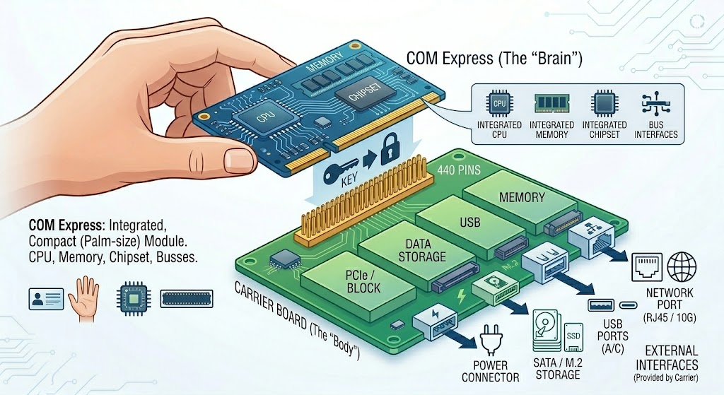
COM Express (Computer-on-Module Express) is a compact standard specification for computer modules. It packs a computer's most core components — CPU, memory, chipset, and core bus interfaces — onto a single circuit board about the size of a business card or the palm of a hand.
A COM Express module cannot function on its own. It must be plugged into a carrier board (baseboard), which provides the specific physical interfaces — power connectors, storage interfaces, USB, and network ports.
Why the module + carrier board model exists
This "core module + carrier board" split solves two recurring problems in industrial and embedded design:
Lower R&D cost, shorter development cycle. Designing a high-frequency, multi-layer CPU core module with dense routing is difficult and expensive. By buying a standardized COM Express module, equipment makers only need to design a simpler carrier board focused on peripheral interfaces.
Field-upgradeable compute. When CPU performance becomes insufficient, there is no need to redesign the device. The old core module is unplugged and a pin-compatible replacement is installed — the carrier board and its I/O design carry over.
The specification was introduced by PICMG (PCI Industrial Computer Manufacturers Group) in 2005 and has gone through several revisions, most recently Rev 3.1 (2022).
High-speed buses carried through the connector
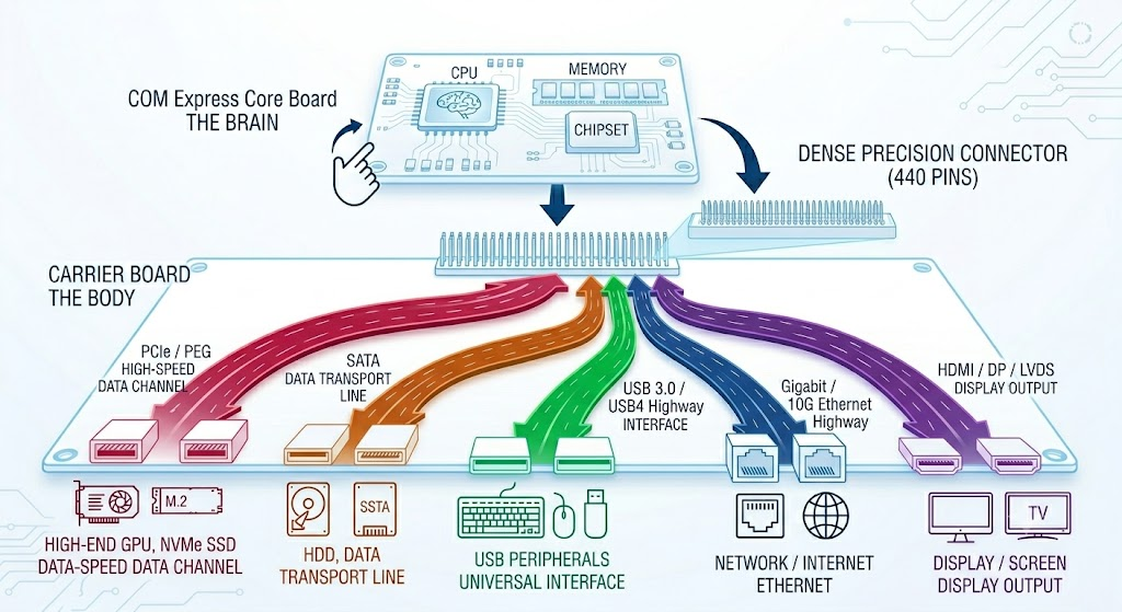
PCIe / PEG — high-speed lanes for graphics cards, NVMe SSDs, or accelerator cards
SATA — interface for conventional hard drives
USB 3.0 / USB4 — general-purpose high-speed peripheral interface
Gigabit / 10-Gigabit Ethernet — network connectivity
HDMI / DisplayPort / LVDS — video output to the carrier board or an external display
These signals cross between the module and the carrier board through a dense, high-precision connector — 220 or 440 pins, depending on form factor.
Four form factors
COM Express defines four standard sizes to match different space and performance requirements:
Form Factor | Dimensions | Typical Use |
|---|---|---|
Basic | 125 × 95 mm | Servers, switches, high-performance industrial systems |
Compact | 95 × 95 mm | Mid-range industrial and display-driven systems |
Mini | 84 × 55 mm | Space-constrained, fanless devices |
Ultra | 110 × 155 mm | High-end computing with extensive I/O |
Type 6, Type 7, and Type 10: the three pinouts in active use
Within the COM Express standard, three pinout types dominate current deployments. Each trades off graphics output against network and high-speed I/O bandwidth differently.
Type 6 | Type 7 | Type 10 | |
|---|---|---|---|
Positioning | All-rounder: compute + display | Server type: networking and data throughput | Mini: smallest footprint, lowest power |
Size | Basic / Compact | Basic | Mini |
Display output | Full (HDMI/DP/DVI) + PEG for discrete GPU | None | One DDI |
Networking | Standard GbE | Up to 4× 10GbE natively | Basic |
PCIe lanes | Standard allocation | Up to 32 lanes | Basic PCIe + USB 3.0 |
Typical applications | Medical imaging, machine vision, gaming machines, digital signage | White-box switch control CPUs, 5G edge servers, industrial routers, network security gateways | Handheld instruments, portable medical devices, in-vehicle infotainment, drone/robot controllers |
Type 7: what was removed, and what replaced it
Type 7 was introduced by PICMG in 2016 (Rev 3.0), purpose-built for networking, servers, and data-center edge computing. It removes all graphics and audio interfaces (HDMI, DisplayPort, VGA, HD Audio) and most USB 2.0 pins, and reallocates that pin budget to:
Four lanes of 10G/25G backplane network channels (KR interface) — the SoC routes four high-bandwidth network signals directly through the connector to the carrier board, which connects to an optical port (SFP+/SFP28) or a PHY chip.
More PCIe lanes (24 → up to 32) — enough bandwidth for the control CPU to reach a switching ASIC (e.g., Marvell Prestera), NVMe SSDs, or accelerator cards.
NC-SI (Network Controller Sideband Interface) — enables server-grade remote management (IPMI/BMC), so a device can be recovered remotely even if it hangs.
How a Type 7 system comes together
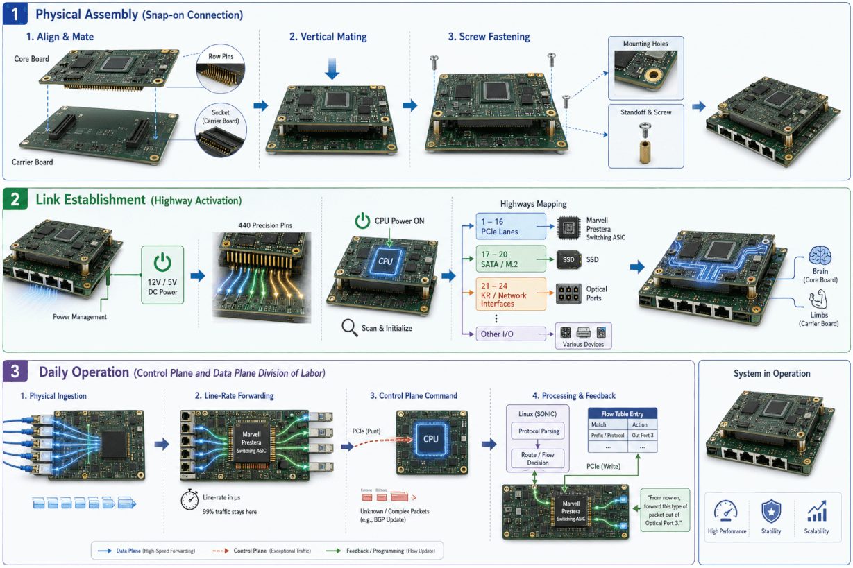
Physical assembly, link establishment, and daily operation happen in three distinct stages:
Physical assembly. The module is pressed vertically into the carrier board's connector(s) — 220 pins for Type 10, 440 pins for Type 6/7 — and secured with standoffs and screws to withstand vibration in industrial and communications environments.
Link establishment. Once seated, the power management chip on the carrier board supplies 12V or 5V DC to the module. The CPU initializes and enumerates the carrier board across the pin groups: PCIe lanes to the switching ASIC for the control path, SATA/M.2 lanes to the boot SSD, and KR lanes to the optical ports.
Daily operation. Once running (for example, a switch booting SONiC), the system settles into a control-plane / data-plane division of labor. The carrier board's switching ASIC receives traffic from the optical port and forwards the large majority of it at line rate without involving the module. When the ASIC encounters an unfamiliar or complex packet — a BGP update, for instance — it passes it to the module over PCIe. The module's control CPU processes the packet in Linux and writes a new flow-table instruction back to the ASIC over PCIe.
Typical application fields
COM Express is deployed across industries that require long product lifecycles, high reliability, and sustained compute performance in harsh environments:
Networking & communications — control planes for industrial switches and routers, 5G vRAN base stations, network security gateways, edge computing appliances, smart NIC host controllers
Medical equipment — ultrasound systems, CT scanners, blood analyzers
Industrial automation — CNC machine tools, machine vision inspection, robot controllers
Military & aerospace — radar signal processing, ruggedized vehicle-mount and airborne computers
Transportation — rail transit control systems, autonomous driving test platforms
2. Why Open Networking Is Shifting from Intel Xeon D to ARM DPUs
For most of its history, the COM Express market — and Type 7 in particular — has been dominated by Intel and AMD x86 processors. That default is now being challenged on three fronts.
Fab capacity is being redirected to AI. As global demand for AI training and inference silicon has surged, Intel's leading-edge fab capacity has been increasingly allocated to high-end server and AI-accelerator products. Mid-range embedded parts — the exact class of chip used in Type 7 control-plane CPUs — have seen extended lead times and periodic allocation shortages. Equipment vendors building on a single-source x86 roadmap have had projects stall on chip availability alone.
x86 power budgets don't fit sealed, fanless enclosures. Embedded Xeon D parts commonly draw 35–67 W. In sealed outdoor cabinets, roadside boxes, or dusty industrial enclosures, that power level typically requires active cooling — and a fan is a moving part that eventually fails in exactly the environments these devices are deployed into.
Heterogeneous SoCs now do more per watt than general-purpose x86. ARM-based network processors such as the Marvell OCTEON 10 family integrate multi-core CPUs, hardware packet-processing engines, and crypto/IPsec ASICs on a single die. For control-plane and data-plane-adjacent workloads, that integration delivers a materially better performance-per-watt profile than a general-purpose x86 core doing the same work in software — without giving up the ability to run a standard Linux/SONiC/VPP software stack.
This is the gap Asteraix's CME102 is built to fill: a COM Express Type 7 module built on Marvell OCTEON 10 silicon instead of x86, aimed specifically at network equipment vendors who need a supply-diversified, lower-power alternative to Xeon D.
3. CME102: The Marvell OCTEON 10 Powered Type 7 Module
The CME102 packages the Marvell® OCTEON™ 10 CN102 DPU as a standards-based, drop-in COM Express® Type 7 Basic module. Within a 33 W, fanless-capable thermal envelope, it combines eight server-class Arm® Neoverse™ N2 cores on a 5 nm process, DDR5 memory, native 10 GbE/PCIe I/O, and on-chip hardware engines for packet processing (VPP) and inline IPsec/crypto offload.
Positioned as a Carrier-Grade Compute Engine Engineered for SONiC, the CME102 pairs naturally with AsterNOS Enterprise SONiC, serving as the control-plane brain for white-box switches and network storage systems while driving data-plane acceleration for edge routers, firewalls (NGFW/UTM), SD-WAN gateways, and 5G small cells.
What it solves for equipment vendors
A standard COM Express footprint lets a carrier board designer treat the compute core as a drop-in part, cutting hardware development time from roughly a year to a few months.
Eight genuine server-class ARM cores run control-plane software at server-class throughput within a 33 W, fanless-capable budget.
Packet processing and IPsec encryption are offloaded to dedicated on-chip hardware engines rather than the CPU cores, so line-rate throughput doesn't come at the cost of general-purpose compute headroom.
Sourcing from Marvell rather than Intel gives vendors a second, independent supply path at a time when x86 embedded parts are allocation-constrained.
Modular, drop-in hardware integration
Designing a board around a networking SoC as complex as the CN102 from scratch carries real schedule and tape-out risk. The CME102 packages that SoC as a standard COM Express Type 7 module, so a carrier board only needs to implement the standard connector interface — the module snaps in and is functional, the way a memory module is. This moves the hardware development cycle from roughly a year down to a few months.
Server-class compute headroom on the control plane
Many embedded chips handle routine packet processing adequately but run out of headroom the moment complex control-plane logic — advanced routing protocols, deep security policy evaluation, traffic auditing — is layered on top. The CME102's eight Arm Neoverse N2 cores deliver a SPECint® rate of 36.5, with 1 MB of dedicated L2 cache per core and 16 MB of shared last-level cache. That is server-class single-thread and multi-core performance, not a repurposed mobile-class design, so control-plane logic runs with headroom to spare rather than becoming the bottleneck.
Hardware-Accelerated Control/Data Plane Decoupling
On a general-purpose CPU — Intel Xeon or an ordinary embedded chip — packet processing, NAT, ACL evaluation, and IPsec encryption all run through the CPU's software protocol stack. Under heavy load, that stack becomes the bottleneck: latency rises, and turning on encryption alone commonly cuts throughput by more than 70%, because compute and forwarding are competing for the same cores.
The CME102 splits this workload at the silicon level. The eight Arm Neoverse N2 cores handle orchestration — Linux, SONiC, VPP control components, BGP/OSPF computation, and management interfaces. Packet forwarding and inline IPsec encryption/decryption run entirely on dedicated on-chip hardware engines, never touching the general-purpose cores. In NGFW and SD-WAN deployments, this decoupling means that even with 100% of traffic encrypted via IPsec and full DPI policies enabled, throughput stays at line rate while Arm core utilization stays below 10%.
Exceptional performance-per-watt at 33 W
The CN102's 5 nm process is the physical basis for this efficiency: roughly triple the throughput of the prior-generation DPU at half the power, while holding total module TDP at 33 W — low enough to support fanless operation even with all eight cores, memory, and network ports under sustained load. That matters directly for equipment that has to sit in sealed, dust- or humidity-exposed enclosures where a fan is a liability rather than a convenience.
Software ecosystem support
The CME102 ships with upstream Linux kernel support, standard Marvell SDK/DPDK PMD drivers, and pre-integrated SAI/VPP plugins. Existing Linux-, SONiC-, or VPP-based network applications migrate onto the module without custom driver development.
Where the CME102 fits in a system
Network switches — control-plane CPU. The CME102 pairs with a switching ASIC in the classic brain-and-muscle model: the ASIC handles Layer 2/3 forwarding and ACL lookups at line rate, while the CME102 runs Linux, SONiC, and routing protocol stacks (BGP, EVPN). Its single-core performance keeps control-plane response in the millisecond range even under heavy route-table churn.
Gateways, routers, firewalls, SD-WAN, NGFW/UTM. This is where the hardware offload architecture described above delivers the most direct result: stateful inspection, DPI, IPsec VPN tunnels, and high-concurrency NAT run at full line rate without the throughput collapse that hits software-stack-based x86 solutions once deep security policy and tunnel encryption are fully engaged.
Network storage devices. The CME102 is not a flash controller replacement — it serves as the storage server's control brain, running Linux, Ceph or ZFS service processes, RAID algorithms, and data management services, paired with up to 48 GB of DDR5 ECC memory and native high-speed network channels to the NVMe array.
5G small cells, vRAN, MEC, industrial controllers, AI edge boxes. The combination of a standard COM Express footprint, on-die 4×10G networking, and a 33 W fanless-capable TDP lets these designs go into sealed outdoor or industrial enclosures — running Kubernetes, lightweight AI inference, or data-collection workloads — without the reliability risk of an active cooling fan.
Device / Scenario | Role of the CME102 |
|---|---|
Switches | Control-plane CPU; runs SONiC and routing protocols |
Routers | Data-plane acceleration; runs routing and VPP control |
Gateways | Gateway services control; offloads NAT and multi-protocol access |
Firewalls / NGFW / UTM | Security policy enforcement, DPI control, VPN tunnel management |
SD-WAN | Edge computing node; offloads high-throughput inline IPsec |
Storage devices | Host controller; runs storage OS (Ceph/ZFS) and data services |
Edge servers | Low-power compute core for containerized (K8s) workloads |
5G equipment | Core processor for vRAN, UPF, and MEC edge applications |
Industrial devices | Ruggedized master control paired with edge AI |
AI edge boxes | Compute engine for real-time inference and video analytics |
4. Architectural Deep Dive & Performance Comparison
Process node and microarchitecture. The Intel Xeon D-1527 is built on a 14 nm node; the more recent Xeon D-1700 (Ice Lake-D) moves to 10 nm. The CME102 goes directly to TSMC's 5 nm process on an Armv9.0-A microarchitecture (Neoverse N2), which is the primary driver of its SPECrate2017_int score of 36.5.
Memory and I/O integration. The CME102 supports DDR5-5600 with ECC, up to 48 GB — roughly double the bandwidth of the Xeon D-1700's DDR4-2933 and the D-1527's DDR4-2133. It integrates 4× 10G-KR plus a GbE MAC on-die; the D-1527 supports only up to 2× 10GbE natively. That integration removes the need for a discrete NIC on the carrier board, which reduces BOM cost and board space.
Data-plane acceleration. The D-1527 offers only the AES-NI instruction set for crypto; the D-1700's Intel QAT is an asynchronous, bolt-on accelerator that still requires CPU coordination. The CME102's Hardware VPP and inline IPsec engines are fully in-silicon and run without CPU involvement, as detailed in Section 3.
Technical Specification | CME102 (Marvell CN102) | Intel® Xeon® D-1700 | Intel® Xeon® D-1527 |
|---|---|---|---|
Process node | 5 nm | 10 nm | 14 nm |
CPU cores | 8× Neoverse N2 (Armv9) | Up to 10C / 20T (Ice Lake) | 4C / 8T (Broadwell) |
Processor TDP | 33 W | Up to 67 W | 35 W |
Fanless operation | Yes (native) | Typically no | Marginal |
Memory | DDR5-5600, ECC | DDR4-2933 | DDR4-2133 |
Integrated 10G Ethernet | 4× 10G-KR + GbE on-die | 4× 10G-KR | Up to 2× 10GbE |
Packet + crypto offload | HW VPP + inline IPsec | Intel® QAT | AES-NI |
Intel does not publish SPECrate2017_int for embedded Xeon D SKUs; the comparison above draws on Marvell, Intel, and COM Express module-vendor datasheets. Representative Xeon D-1700 SKUs: D-1736NT (8C) and D-1746TER (10C), 67 W module TDP. Power and throughput figures for the CME102 reflect testing at 25 °C ambient temperature under full 4× 10G IPsec load; production deployments in sealed or higher-ambient enclosures should validate thermal margin against the target chassis.