
1 Background
In modern cloud data center networks and AI computing center networks, high availability and business continuity are core metrics of network infrastructure capability. As network scale expands rapidly, routine maintenance, version upgrades, vulnerability remediation, and software fault recovery on switch operating systems have become increasingly frequent operations. Achieving smooth evolution and seamless upgrades of network devices without disrupting tenants' critical business and distributed computing workloads has become a pressing challenge in large-scale data center network operations.
During a software reload, the traditional Cold Reboot approach interrupts the switch’s control plane and data forwarding plane simultaneously. This typically triggers a cascade of effects — including protocol neighbor teardown and route reconvergence — resulting in traffic outages lasting several minutes, which significantly impacts business workloads with stringent network continuity requirements, such as cloud computing and AI training and inference. To reduce the impact of control-plane software maintenance, upgrades, and fault recovery on business forwarding, Warm Reboot technology was developed. Its core objective is to keep the data plane forwarding continuously throughout a control-plane software restart, minimizing business disruption to the greatest extent possible.
Table 1 Cold Reboot vs. Warm Reboot Comparison
Dimension | Cold Reboot | Warm Reboot |
|---|---|---|
Forwarding interruption time | > 180 seconds | Sub-second to a few seconds |
Hardware and link state | ASIC hardware reset; PHY/SerDes reinitialized; physical links transition Down/Up | ASIC remains powered and retains its existing hardware forwarding state; PHY/SerDes state is preserved; physical links remain Up |
AsterNOS’s support for Warm Reboot stems from the decoupled control-plane/data-plane architecture, modularity, and containerization that the SONiC architecture provides. Unlike traditional, closed network operating systems in which software processes are tightly coupled to the underlying hardware state, AsterNOS runs core network functions and system services as containerized, modular components, and uses a Redis database to centrally manage and synchronize system configuration and inter-module runtime state — laying the foundation for persisting and rapidly restoring system state.
Built on this decoupled architecture, AsterNOS’s Warm Reboot minimizes the impact on business forwarding during control-plane software restarts. Its core mechanism works as follows: during a switch control-plane software restart, key system configuration and runtime state are persisted, while the existing forwarding state programmed into the underlying ASIC is preserved, allowing the data plane to continue forwarding traffic using its existing hardware forwarding tables. Once the control-plane software completes its restart and resumes operation, a state synchronization mechanism restores normal management of the data plane — achieving both rapid control-plane recovery and business continuity.
2 Working Principles
2.1 Basic Concepts
Table 2 Warm Reboot Terminology and Definitions
Term | Definition |
Current View | The actual mapped state that was already programmed into the ASIC prior to Warm Reboot, and that the hardware continues to use for data forwarding throughout the control-plane restart. At system startup, this state is reclaimed and reconstructed by LibSAI by reading a pre-saved serialized file. |
Temporary View | The target state set recalculated by upper-layer business modules and Orchagent after the control plane completes its software reload, based on historical data restored from the Redis database. This view is compared against the Current View and does not directly overwrite the underlying hardware. |
Virtual Object ID (VID) | A software virtual identifier assigned by the SAI abstraction layer to each network logical object (e.g., interfaces, routes, ACLs). |
Real Object ID (RID) | A physical identifier assigned by the underlying ASIC and SDK to hardware resources. |
State Reconciliation | During the Warm Reboot reload phase, the control plane compares the expected SAI target state reconstructed from the database (Temporary View) against the actual hardware-mapped state recovered from the underlying serialized file (Current View), programming only the differences and removing redundant entries — without rebuilding the hardware tables from scratch. |
2.2 System Architecture and Design Principles
2.2.1 Overall Architecture
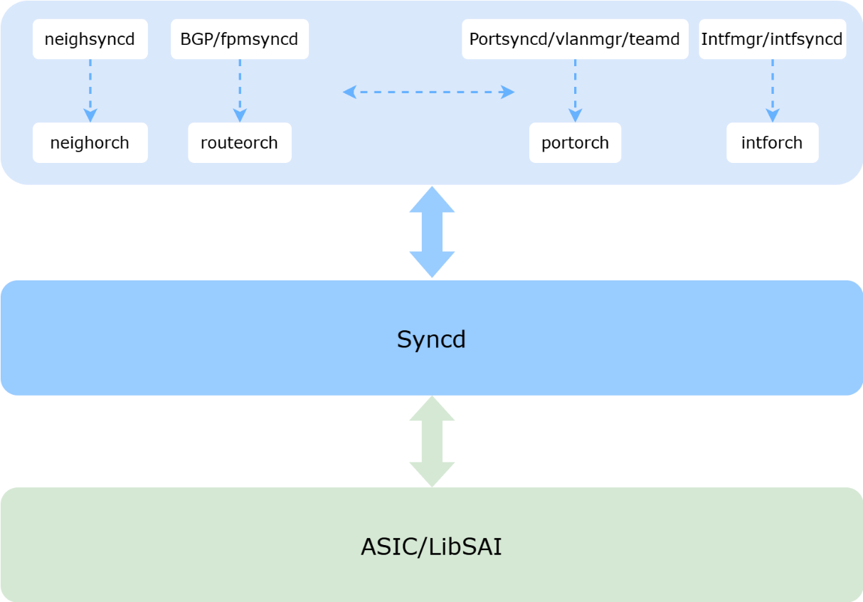
The goal of Warm Reboot is to restart and upgrade AsterNOS software with minimal impact on the data plane. Warm restarts of individual processes and containers also fall within this scope.
The Warm Reboot process can be divided into three layers:
1. Network applications and Orchagent: Each application and its corresponding Orchagent submodule work together to restore the original data and generate the incremental data needed to drive the Warm Reboot startup.
2. Syncd: Before the restart, Syncd dumps the ASIC_DB data. After the Syncd container is warm-restarted, it reads the dumped data to reconstruct, in memory, the software’s internal state as it existed before the restart. Syncd’s own recovery must not affect ASIC state. It receives change data from Orchagent, performs any necessary transformation, and passes it to LibSAI/ASIC.
3. LibSAI/ASIC: During the software reload, the ASIC must retain its existing hardware forwarding entries and continue operating without interruption, ensuring data-plane forwarding is never disrupted. As the hardware abstraction layer, LibSAI must support warm takeover: at startup, it reads the serialized file preserved before the restart to take over the ASIC while it continues operating.
2.2.2 Workflow
2.2.2.1 System-Level Warm Reboot Shutdown Path
The core of the system-level Warm Reboot shutdown path is to safely suspend the control-plane containers while preserving the ASIC’s existing forwarding state, and to serialize the SAI- and ASIC-related software state to external persistent storage — ensuring the hardware state is preserved throughout the control-plane restart. Using the BGP, teamd, and SWSS Docker containers as an example, the steps of the Warm Reboot shutdown path are as follows:
1. Graceful protocol exit: Trigger graceful-restart mechanisms for network protocols (e.g., BGP Graceful Restart), signaling peers to retain the forwarding table without withdrawal for a preset hold time; gracefully stop the teamd link-aggregation process and extend the neighbor timeout to prevent the physical link state from immediately transitioning to Down.
2. Control-plane freeze: Disable underlying hardware aging mechanisms (e.g., MAC address aging) to prevent unintended aging of valid entries while the CPU is offline; freeze the orchestration layer’s programming threads and write a “warm-restart flag” to the system database.
3. State persistence: Rapidly dump the full in-memory database to an externally mounted persistent directory to ensure no data loss.
4. Hardware state lock: Syncd instructs the underlying hardware to enter warm-restart preparation mode. The LibSAI layer serializes and exports the ASIC’s and SAI’s current hardware mappings and state to a standalone file, then safely exits the Syncd container without performing a physical ASIC reset.
5. Fast-boot restart: Use kexec to fast-boot directly into warm-restart mode, bypassing the time-consuming hardware self-test process.
2.2.2.2 System-Level Warm Reboot Startup Path
The core of the system-level Warm Reboot startup path is to rapidly restore control-plane state, reconstruct the logical view, and complete state reconciliation with the hardware that has continued running throughout.
1. Data reload: Once the system detects the warm-restart startup parameter, it prioritizes bringing up the database container, automatically restoring the full pre-shutdown runtime data from the persistent directory.
2. Smooth hardware takeover: The Syncd container starts and reads the serialized file saved before shutdown. Without affecting the physical forwarding plane, it reconstructs the driver’s internal state and retakes control of the ASIC.
3. View reconstruction: The Orchagent container starts and instructs the underlying layer to enter “Temporary View” construction mode. Each business module replays its full dataset based on the restored database; once replay completes, the State Reconciliation process is triggered.
4. Upper-layer protocol recovery: BGP, teamd, and other protocol containers are brought up together with SWSS. Until the internal control-plane state is fully aligned with the underlying hardware, the system withholds responses to externally driven protocol changes. Once alignment is complete, each module finalizes convergence.
2.2.2.3 View Reconciliation Mechanism and Matching Algorithm
To seamlessly reconcile the control-plane state reconstructed after Warm Reboot with the underlying hardware state that was never interrupted, AsterNOS employs a view reconciliation mechanism and matching algorithm that avoids destructive, full-table overwrites of the hardware. Its main steps are as follows:
1. Dual-view construction:
a. Current View: The actual state already programmed into the ASIC before the restart, which the hardware continues to use throughout the restart.
b. Temporary View: The target state recalculated from the database and expected to be programmed following this control-plane Warm Reboot.
2. Fast-match phase:
a. The algorithm first identifies “fixed internal switch objects” that remain unchanged throughout Warm Reboot (invariants, such as physical ports, hardware queues, and schedulers) and uses them as anchors.
b. It compares the VIDs of these objects between the Temporary View and the Current View. If the VIDs match, their corresponding physical RIDs are guaranteed to match as well, and the algorithm marks them directly as MATCHED, skipping further deep traversal and substantially reducing algorithmic overhead.
3. Deep transition comparison phase:
a. Using the invariants as anchors, the algorithm recursively compares each object in the Temporary View, working downward.
b. For each temporary object, it searches the Current View for the best candidate for reuse. If no match is found, a create instruction is issued to the hardware; if the best match is found but its attributes differ, a differential update instruction is issued; if an exact match with identical attributes is found, the existing entry is reused directly with no hardware write.
4. Stale-entry cleanup: Once the comparison completes, the algorithm scans the Current View for all objects that were not marked MATCHED and whose reference count has dropped to zero, and safely removes them from the hardware. This consistency-first strategy ensures the control plane and data plane converge on a consistent state.
3 Typical Application Scenarios
3.1 AI Computing Centers: Ensuring Business Continuity for Large-Scale Distributed Training
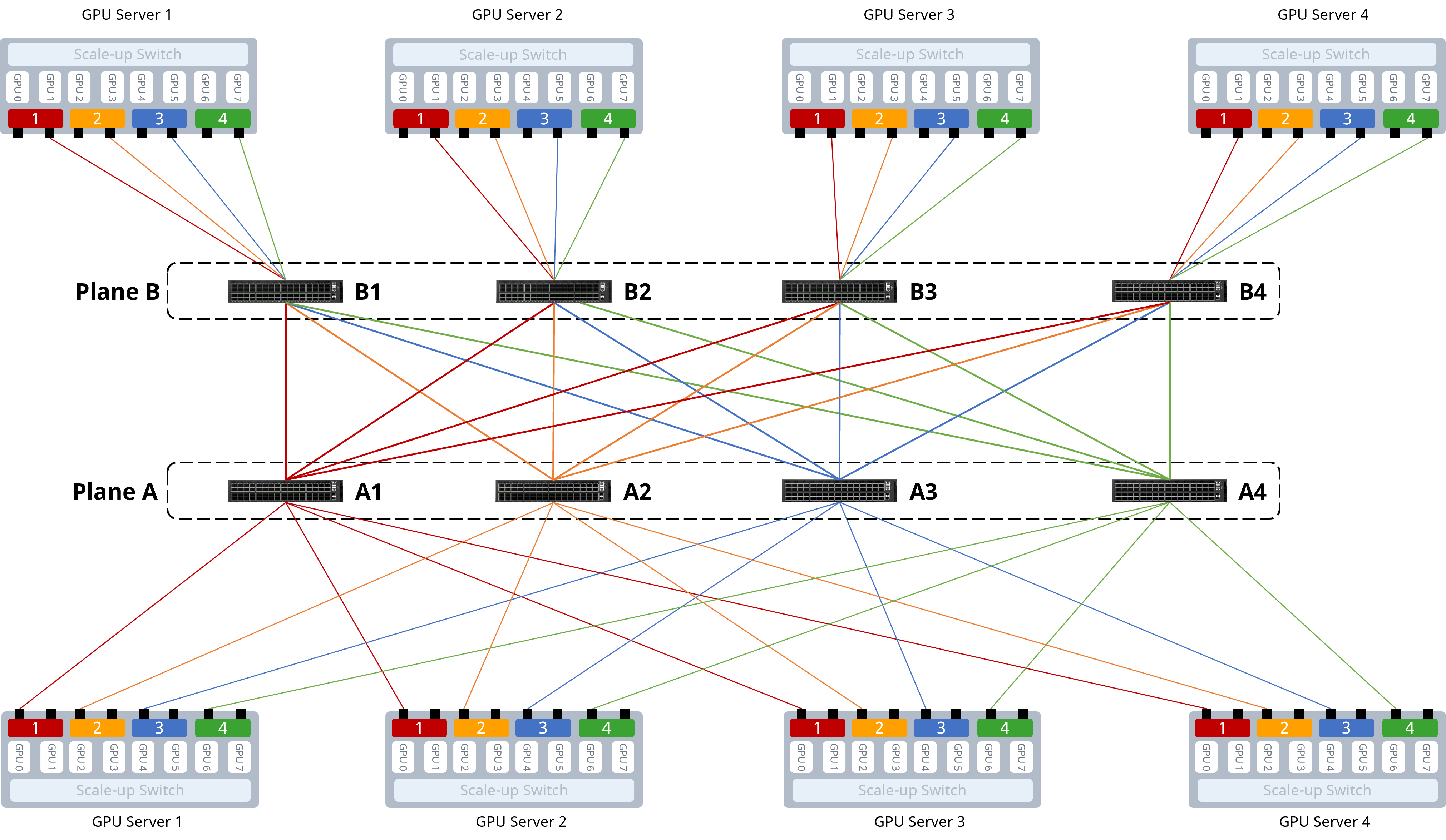
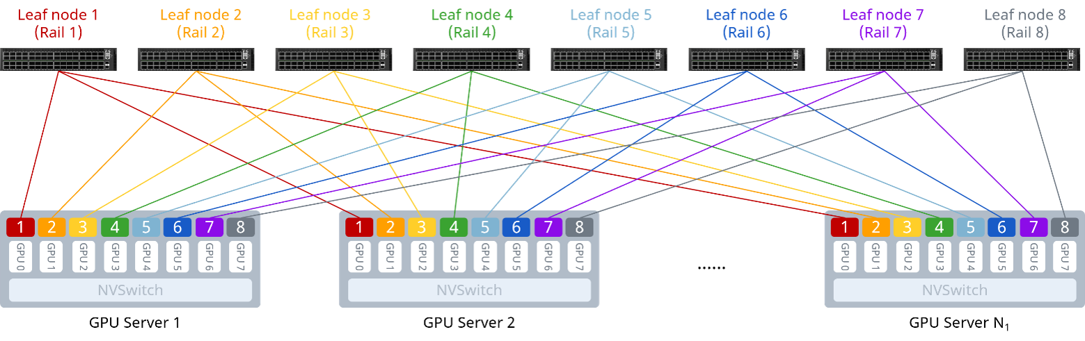
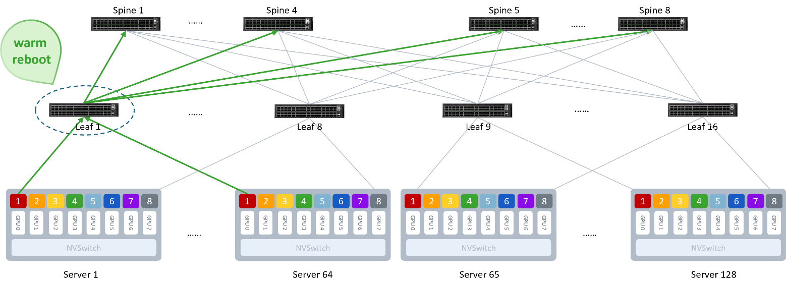
When building AI distributed training clusters at the scale of thousands to tens of thousands of GPUs, large-model training cycles often span weeks or even months. Over these long, high-load training runs, switch software version upgrades and vulnerability remediation are unavoidable operational tasks. Traditional software upgrades require a full cold reboot, causing widespread network outages across the cluster — directly interrupting running distributed compute jobs and leaving GPU compute capacity idle and wasted. With Warm Reboot technology, operations teams can perform seamless, in-service upgrades of the switch operating system. During the system Warm Reboot process, the underlying switching ASIC continues forwarding traffic, enabling smooth, hitless network maintenance and improving the overall availability of the compute cluster.
3.2 Cloud Data Centers: Enabling Smooth In-Service Upgrades for Critical Business Traffic
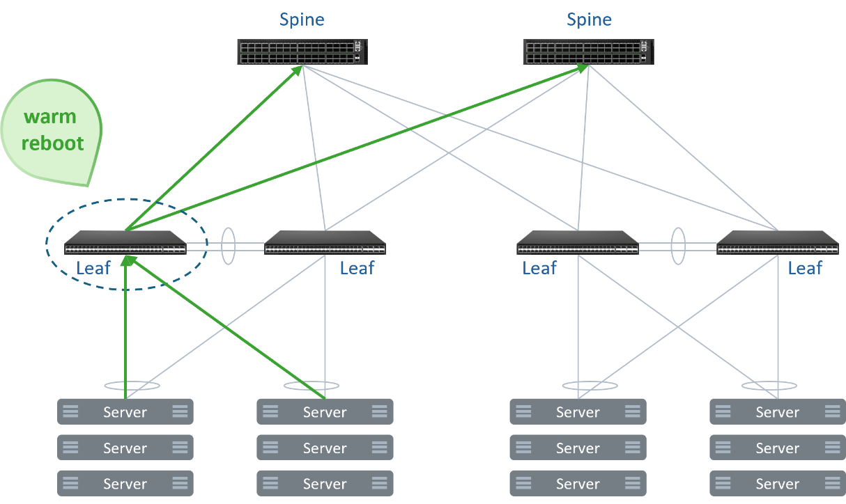
In multi-tenant public and private cloud data centers, the network carries substantial business traffic that is highly sensitive to packet loss and latency — such as online financial transactions, real-time audio/video, and cloud storage data synchronization. Traditional switch upgrades typically require complex traffic-diversion procedures; a direct cold reboot would cause a traffic black hole and business disruption lasting several minutes on Spine or Leaf nodes. With Warm Reboot technology, network operations teams can perform smooth, in-service software upgrades on production switches while live business traffic continues to flow. As the control-plane operating system reloads and routing protocols (such as BGP) perform graceful restart and state reconstruction, the underlying hardware ASIC continues providing line-rate data forwarding based on the forwarding tables locked and preserved before the restart. This mechanism enables cloud data centers to achieve business-transparent, hitless upgrades and smooth data-plane transitions during network version iterations, new feature rollouts, or emergency security patching — making the evolution of the underlying network infrastructure transparent to cloud tenants.