Small-Scale AI Cluster Backend Network Best Practices: Rail-Only Single-Tier Configuration Guide
Preface
This document provides a detailed guide for using Asteraix data center switches to build a standardized network solution for small-scale AI computing backend networks. It adopts a single-tier topology based on a Rail-only architecture, including configuration guidance and operational maintenance procedures.
Target Audience
This manual is intended for solution planning, design, and on-site deployment personnel. Readers should have the following background knowledge:
- Familiarity with Asterfusion data center network switch products
- Understanding of RoCE, PFC, and ECN technologies
Revision History
| Date | Version | Change Description |
| 2026-02-02 | V1.0 | Initial release |
1 Overview
Small-scale AI cluster backend networks can be deployed using a Rail-only architecture.
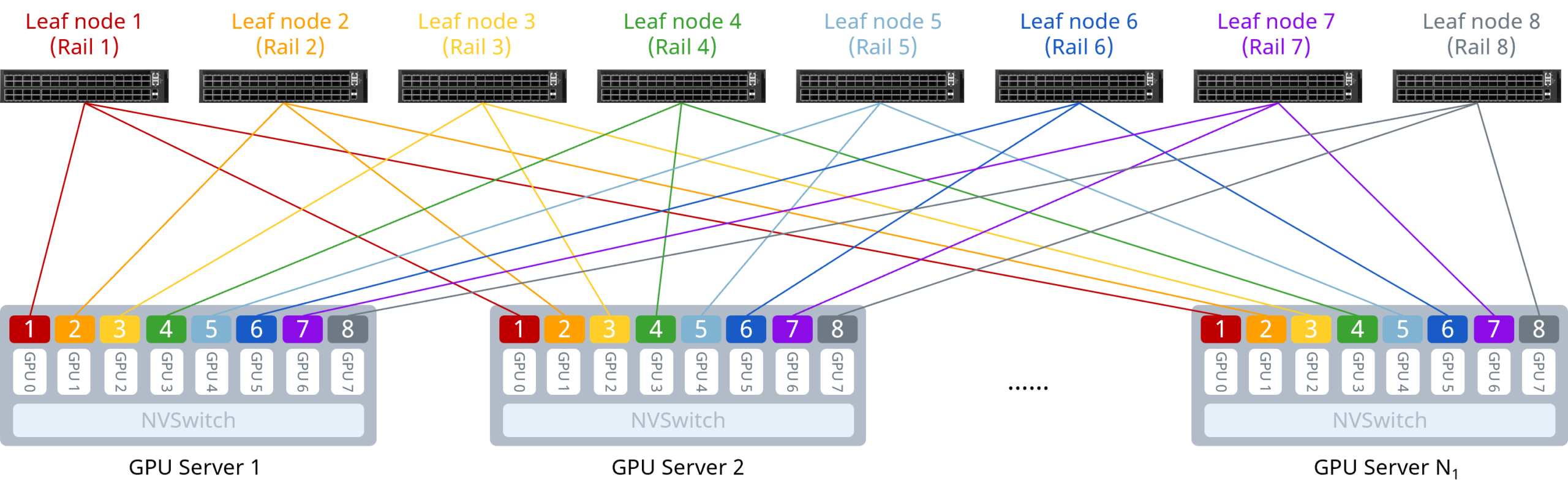
As shown above, the Rail-only architecture uses a single-tier network design. It physically partitions the entire cluster network into 8 independent rails. GPU-to-GPU communication across nodes is carried over the same rail, and intra-rail communication can be achieved in a single hop.
Compared to a traditional Clos architecture, Rail-only eliminates the Spine tier. Reducing the number of switches and optical modules at the network layer, it lowers hardware costs significantly. It is a purpose-built low-cost, high-performance network architecture for large-scale AI model training, well-suited to small-scale compute clusters.
2 Typical Configuration Example
2.1 Network Topology
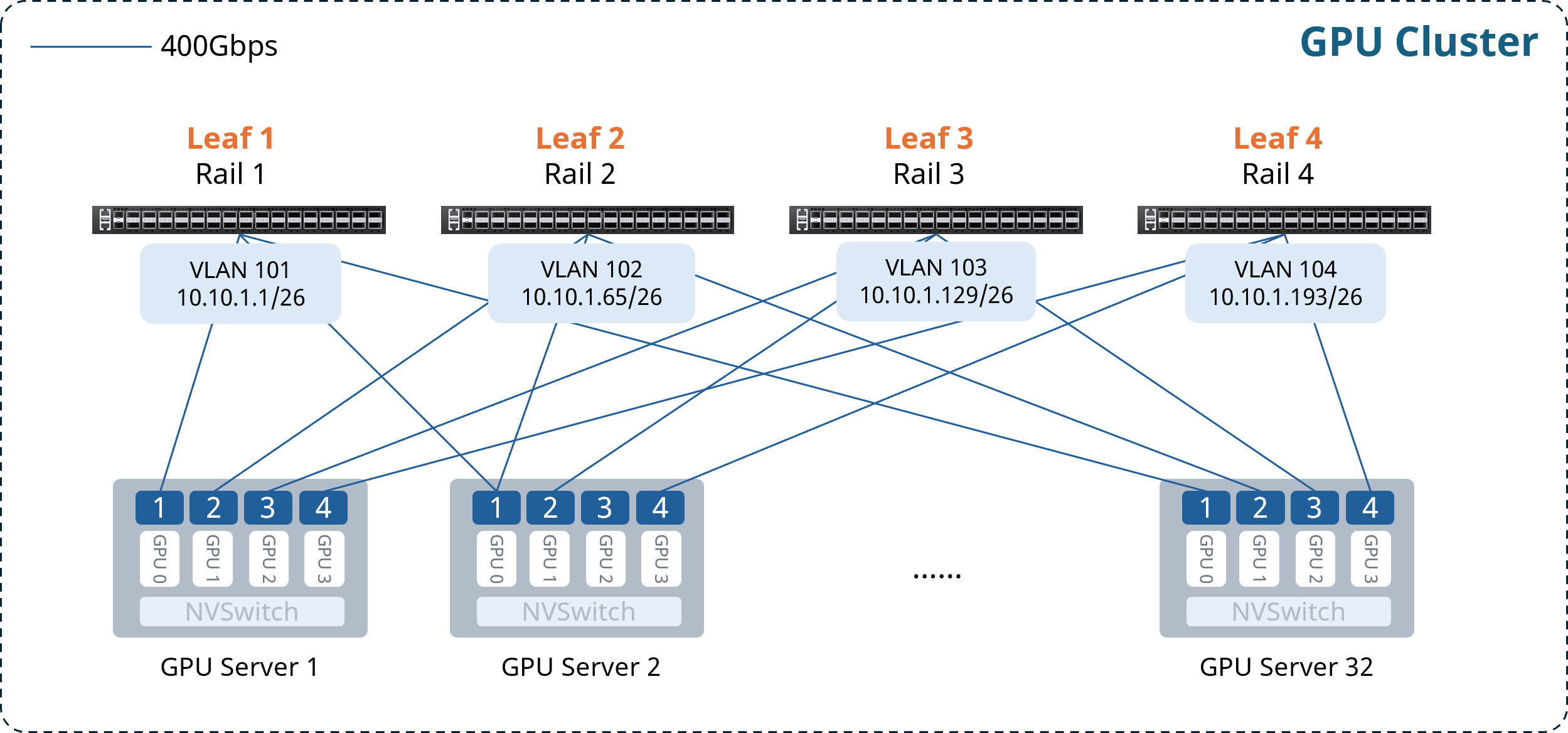
The following example illustrates building an AI cluster of 32 compute nodes (4 GPUs per server, 128 GPUs total) using 4 CX732Q-N switches as Leaf nodes. The key configuration concepts are:
- Each GPU has a dedicated NIC. Each server’s NICs connect to Leaf switches following the pattern NIC1→Leaf1, NIC2→Leaf2, …, so that each Rail has its own subnet, with the Leaf switch acting as the default gateway for the Rail.
- The network uses a single-tier Clos architecture — no Spine layer.
- Leaf switches enable one-click RoCE to provide a lossless network.
Gateway VLAN IP address allocation is as follows:
Table 2-1 Gateway VLAN IP Address Allocation
| Device | VLAN | Gateway IP Address |
| Leaf1 | 101 | 10.10.1.1/26 |
| Leaf2 | 102 | 10.10.1.65/26 |
| Leaf3 | 103 | 10.10.1.129/26 |
| Leaf4 | 104 | 10.10.1.193/26 |
2.2 Configuration Overview
Table 2-2 Configuration Overview
| Operation | Configuration Steps |
| Configure Leaf Switch | (Optional) Configure NIC-side port breakout |
| Configure gateway VLAN and IP address | |
| Enable one-click RoCE |
2.3 Configuring the Leaf Switch
2.3.1 (Optional) Configure NIC-side Port Breakout
For scenarios using CX864E-N switches with 400G NICs, the downlink 800G ports need to be broken out into two 400G ports.
Table 2-3 Configure NIC-side Port Breakout
| Step Description | Leaf1 |
| Enter global configuration mode | configure terminal |
| Break out upper-half 800G ports | interface range ethernet 0/0-0/504 breakout 2x400G[200G] ! |
| If bulk interface config is not supported in the current version, execute individually: | interface ethernet 0/0 breakout 2x400G[200G] ! …… |
After completing the configuration above, you can verify the interface status with the show interface summary command.
2.3.2 Configure Gateway VLAN and IP Address
Table 2-4 Configure VLAN and Interface IP Address
| Step Description | Leaf1 |
| Set device hostname | hostname Leaf1 |
| Enter global configuration mode | configure terminal |
| Create gateway VLAN and assign IP address | vlan 101 ! interface vlan 101 ip address 10.10.1.1/26 exit ! |
| Add interfaces to the VLAN | interface range ethernet 0/0-0/248 switchport access vlan 101 ! |
| If bulk config is not supported, execute individually: | interface ethernet 0/0 switchport access vlan 101 ! …… |
After completing the configuration, use show vlan summary to verify the VLAN configuration.
2.3.3 Enable One-Click RoCE
The CX-N series switch supports queues 0–7 (8 queues total). Queues 3 and 4 are lossless queues (up to 2 lossless queues are supported); all other queues are lossy queues.
The default template uses the system default DSCP mapping. Queues 3 and 4 enable PFC and ECN. Queues 6 and 7 are configured with strict priority scheduling.
When creating a template, the following three parameters can be specified:
- cable-length: Specifies the cable length in meters, which affects the PFC and ECN parameter calculations. Options: 5m / 40m / 100m / 300m. If no exact match, choose the nearest value (e.g., for 10m actual cable length, select 5m).
- incast-level: Specifies the traffic Incast model, affecting PFC parameter calculations. Options: low (e.g., 1:1) / medium (e.g., 3:1) / high (e.g., 10:1). In GPU backend networks, low is generally recommended.
- traffic-model: Specifies the traffic type — throughput-sensitive, latency-sensitive, or balanced — which affects ECN parameter calculations. Options: throughput / latency / balance. In GPU backend networks, balance or throughput mode is generally recommended.
If the lossless RoCE configuration provided does not fully fit your business scenario, refer to Section 3.1 RoCE Tuning/Optimization for configuration adjustments and parameter fine-tuning to achieve optimal performance.
Table 2-5 Enable Easy RoCE
| Step Description | Leaf1 |
| (Optional) Modify lossless queues. Requires saving config and reloading to take effect. | no priority-flow-control enable 3 no priority-flow-control enable 4 priority-flow-control enable queue-id write reload |
| Select the one-click RoCE template and apply it to all interfaces | qos roce lossless cable-length 5m incast-level low traffic-model throughput qos service-policy roce_lossless_5m_low_throughput |
After completing the configuration, use show qos roce to verify the RoCE configuration. Example output:
Leaf1# show qos roce
Notice: Displaying configurations of in-use RoCE profiles
==> RoCE Profile: roce_lossless_5m_low_throughput | RoCE Policy Map: roce_lossless_5m_low_throughput_400g <==
+--------------------+-----------------+-----------------------------------------------------+
|                    | Operational     | Description                                         |
+====================+=================+=====================================================+
| Mode               | Lossless        | QoS RoCE mode                                       |
+--------------------+-----------------+-----------------------------------------------------+
| Status             | Bind: 0/0-0/248 | QoS RoCE binding status                             |
+--------------------+-----------------+-----------------------------------------------------+
| Cable Length       | 5m              | Cable length in meters for QoS RoCE lossless config |
+--------------------+-----------------+-----------------------------------------------------+
| Congestion-Control | -               | -                                                   |
|  - Congestion Mode | ECN             | Congestion control mode                             |
|  - Enabled TC      | 3,4             | Congestion control config enabled traffic class     |
|  - Max Threshold   | 4697728         | Congestion control config max threshold             |
|  - Min Threshold   | 2000000         | Congestion control config max threshold             |
+--------------------+-----------------+-----------------------------------------------------+
| PFC                | -               | -                                                   |
|  - PFC Priority    | 3,4             | PFC enabled switch priority                         |
|  - TX Status       | Enabled         | PFC RX status                                       |
|  - RX Status       | Enabled         | PFC TX status                                       |
+--------------------+-----------------+-----------------------------------------------------+
| Trust              | -               | -                                                   |
|  - Trust Mode      | DSCP            | Trust setting for packet classification             |
+--------------------+-----------------+-----------------------------------------------------+
====> RoCE DSCP->SP Mapping Configurations <====
+-------------------------+-------------------+
| DSCP                    | Switch Priority   |
+=========================+===================+
| 0,1,2,3,4,5,6,7         | 0                 |
| 8,9,10,11,12,13,14,15   | 1                 |
| 16,17,18,19,20,21,22,23 | 2                 |
| 24,25,26,27,28,29,30,31 | 3                 |
| 32,33,34,35,36,37,38,39 | 4                 |
| 40,41,42,43,44,45,46,47 | 5                 |
| 48,49,50,51,52,53,54,55 | 6                 |
| 56,57,58,59,60,61,62,63 | 7                 |
+-------------------------+-------------------+
====> RoCE SP->TC Mapping & ETS Configurations <====
+-------------------+--------+----------+
| Switch Priority   | Mode   | Weight   |
+===================+========+==========+
| 6                 | SP     | -        |
| 7                 | SP     | -        |
+-------------------+--------+----------+
====> PFC Profile Configurations <====
+----------------------------------------------+-------------------+
| Profile Name                                 | Switch Priority   |
+==============================================+===================+
| egress_lossless_profile                      | 3,4               |
| egress_lossy_profile                         | 0,1,2,5,6,7       |
| ingress_lossy_profile                        | 0,1,2,5,6,7       |
| pg_lossless_10000_40m_profile                | 3,4               |
| roce_lossless_5m_low_throughput_400g_profile | 3,4               |
| roce_lossless_5m_low_throughput_800g_profile | 3,4               |
+----------------------------------------------+-------------------+
3 Maintenance
3.1 RoCE Tuning/Optimization
When the lossless RoCE configuration provided does not fully suit your business scenario, you can perform configuration adjustments and parameter fine-tuning via CLI commands to achieve optimal performance.
3.1.1 Modify DSCP Mapping
Table 3-1 Modify DSCP Mapping
| Operation | Command |
| View running-config to get the DSCP map name | show running-config |
| Enter DSCP mapping configuration view | diffserv-map type ip-dscp roce_lossless_diffserv_map |
| Enter global configuration mode | configure terminal |
| Configure mapping of a specific DSCP value to a CoS value | ip-dscp dscp_value cos cos_value |
| Map all DSCP values to the same CoS value | default cos_value |
| Restore the system default DSCP mapping | default copy |
Note: CoS value represents the queue ID to which the packet is mapped.
3.1.2 Modify Queue Scheduling Policy
If the interface is already bound to a lossless RoCE policy, unbind it first before modifying the queue scheduling policy.
Table 3-2 Modify Queue Scheduling Policy
| Operation | Command |
| View running-config to get the policy name | show running-config |
| Enter global configuration mode | configure terminal |
| Enter lossless RoCE policy configuration view | policy-map roce_lossless_name |
| Configure SP (Strict Priority) scheduling | queue-scheduler priority queue queue-id |
| Configure DWRR scheduling (queue-weight is the scheduling weight percentage, range 1–100) | queue-scheduler queue-limit percent queue-weight queue queue-id |
3.1.3 Adjust PFC and ECN Thresholds
ECN thresholds are adjusted through min_th, max_th, and probability:
- min_th sets the lower absolute threshold for explicit congestion notification, in bytes. When the queue length reaches this value, the interface begins probabilistically marking the ECN field of packets as CE (Congestion Experienced).
- max_th sets the upper absolute threshold for explicit congestion notification, in bytes. When the queue length reaches this value, the interface marks all packets’ ECN fields as CE.
- probability sets the maximum marking probability (integer, range [1,100]).
PFC thresholds are adjusted by modifying the dynamic threshold coefficient dynamic_th: PFC threshold = 2^dynamic_th × remaining available buffer. Other parameters can remain unchanged.
For the CX864E-N device, the recommended parameter values are:
- PFC dynamic_th: 1, 2, or 3
- WRED min (Bytes): 1,000,000 / 2,000,000 / 3,000,000
- WRED max (Bytes): 8,000,000 / 10,000,000 / 12,000,000
- WRED probability (%): 10 / 30 / 50 / 70 / 90
For other device models, the recommended parameter values are:
- PFC dynamic_th: 1, 2, or 3
- WRED min (Bytes): 1,000,000 / 2,000,000 / 3,000,000
- WRED max (Bytes): 4,000,000 / 5,000,000 / 6,000,000
- WRED probability (%): 10 / 30 / 50 / 70 / 90
Note: ECN should be tuned first, then PFC. The following ordering rule must be observed: WRED Min < WRED Max < PFC xON < PFC xOFF. This ensures ECN can trigger early during congestion to adjust the rate, avoids unnecessary PFC triggering, and also ensures PFC fires when necessary to prevent packet loss.
Table 3-3 Adjust PFC and ECN Thresholds
| Operation | Command |
| View running-config to get the WRED and Buffer template names generated by Easy RoCE | show running-config |
| Enter global configuration mode | configure terminal |
| Enter the ECN configuration view of the template | wred roce_lossless_ecn |
| Adjust ECN threshold | mode ecn gmin min_th gmax max_th gprobability probability |
| Enter the PFC configuration view of the template | buffer-profile roce_lossless_profile |
| Adjust PFC threshold | mode lossless dynamic dynamic_th size size xoff xoff xon-offset xon-offset |
3.2 Common Operational Commands
3.2.1 Interface Status
Table 3-4 Interface Status Information
| Operation | Command |
| View interface status | show interface summary |
| View Layer 3 interface IP configuration and status | show ip interfaces |
| View VLAN configuration | show vlan summary |
| View interface counters | show counters interface |
3.2.2 Common Table Entries
Table 3-5 Common Table Entries
| Operation | Command |
| View LLDP neighbor information | show lldp neighbor {summary|interface interface-name} |
| View local MAC address table | show mac-address |
| View local ARP table | show arp |
3.2.3 RoCE Statistics
Table 3-6 RoCE Statistics Information
| Operation | Command |
| View RoCE configuration | show qos roce [all|summary|RoCE_profile_name] |
| View interface-to-policy binding | show interface policy-map |
| View RoCE statistics counters | show counters qos roce interface ethernet interface-name queue queue-id |
| Clear all interface RoCE statistics | clear counters qos roce |
| View PFC counters | show counters priority-flow-control |
| Clear PFC counters | clear counters priority-flow-control |
| View ECN counters | show counters ecn |
| Clear ECN counters | clear counters ecn |
4 Appendix
4.1 Configuration Files
4.1.1 Leaf1
!
hostname Leaf1
!
interface loopback 0
 ip address 10.1.0.111/32
!
interface vlan 101
 ip address 10.10.1.1/26
exit
!
interface range ethernet 0/0-0/248
 switchport access vlan 101
!
qos roce lossless cable-length 5m incast-level low traffic-model throughput
qos service-policy roce_lossless_5m_low_throughput
!
4.1.2 Leaf2
!
hostname Leaf2
!
interface loopback 0
 ip address 10.1.0.112/32
!
interface vlan 102
 ip address 10.10.1.65/26
exit
!
interface range ethernet 0/0-0/248
 switchport access vlan 102
!
qos roce lossless cable-length 5m incast-level low traffic-model throughput
qos service-policy roce_lossless_5m_low_throughput
!
4.1.3 Leaf3
!
hostname Leaf3
!
interface loopback 0
 ip address 10.1.0.113/32
!
interface vlan 103
 ip address 10.10.1.129/26
exit
!
interface range ethernet 0/0-0/248
 switchport access vlan 103
!
qos roce lossless cable-length 5m incast-level low traffic-model throughput
qos service-policy roce_lossless_5m_low_throughput
!
4.1.4 Leaf4
!
hostname Leaf4
!
interface loopback 0
 ip address 10.1.0.114/32
!
interface vlan 104
 ip address 10.10.1.193/26
exit
!
interface range ethernet 0/0-0/248
 switchport access vlan 104
!
qos roce lossless cable-length 5m incast-level low traffic-model throughput
qos service-policy roce_lossless_5m_low_throughput
!