
Foreword
Traditional large-model compute clusters commonly adopt symmetric topologies such as Clos/Fat-Tree and ROFT (Rail-Optimized Fat-Tree). As cluster scale grows and inference workloads become more complex, these topologies increasingly expose problems such as high hardware cost, load-balancing failures under asymmetric traffic, and large tail-latency jitter. The asymmetric dual-plane networking approach removes the spine layer entirely: leaf switches are split into groups that are fully interconnected to form a complete bipartite graph, with single-rail and multi-rail access combined. This yields a constant two-hop forwarding distance across the entire network and, paired with deterministic routing, eliminates avoidable congestion at the architectural level.
This paper focuses on the design of an asymmetric dual-plane inference network for AI compute, built around Asteraix's 800G high-density-port data center switches as the core hardware platform, using asymmetric dual-plane networking to deliver a standardized, deployable solution.
Intended Audience
This guide is primarily intended for solution planning/design staff and on-site implementation personnel. Relevant personnel should have the following capabilities:
Familiarity with Asteraix data center network switch products
An understanding of RoCE, RDMA, and the PD-disaggregated (Prefill-Decode) LLM inference architecture, among other topics
Revision History
Date | Version | Revision Notes |
|---|---|---|
2026-09-18 | V1.0 | Initial release |
1 Introduction
Large-model inference is now evolving from the traditional "unified training-and-inference cluster" model toward a dedicated Prefill-Decode (PD) disaggregated inference architecture. PD disaggregation decouples the compute-intensive prompt-processing stage (Prefill) from the memory-access-intensive token-generation stage (Decode) into separate instance pools, significantly improving inference throughput and resource utilization. However, this architectural shift places entirely new and stringent demands on the underlying network:
KV Cache cross-node transfer becomes the dominant traffic pattern: After a Prefill node generates the KV Cache, it must be transferred to the Decode node at high bandwidth and low latency; the transfer size varies dynamically, from megabytes to gigabytes.
Traffic is highly asymmetric: The relationship between the KV Cache's source node (Prefill) and destination node (Decode) is unpredictable, resulting in highly uneven NIC load — the load-balancing mechanisms of traditional symmetric topologies break down.
Extreme sensitivity to tail latency: Time-to-first-token (TTFT) and time-per-output-token (TPOT) directly determine the user experience; any congestion or jitter at the network layer is cascaded and amplified.
Traditional large-model compute clusters commonly use symmetric topologies such as Clos/Fat-Tree and ROFT, which were originally designed to serve symmetric collective-communication patterns in training scenarios, such as All-Reduce and All-to-All. When reused directly for PD-disaggregated inference, they increasingly expose problems such as hash polarization, structural congestion, large tail-latency jitter, and high hardware cost. The asymmetric dual-plane networking approach proposed in this solution is a network architecture purpose-built for PD-disaggregated inference. By removing the spine layer, forming a complete bipartite graph through fully interconnected leaf-switch groups, combining single-rail and multi-rail access, maintaining a constant two-hop forwarding distance across the network, and pairing this with deterministic routing, it eliminates avoidable congestion in PD-disaggregated scenarios at the architectural level — providing an optimal network foundation for large-scale GPU inference clusters.
2 PD-Disaggregated Inference Architecture and Network Challenges
2.1 Overview of the PD-Disaggregated Architecture
In large-model inference, PD disaggregation has become the core architecture for improving system efficiency:
Prefill stage: Responsible for ingesting the user's full input prompt and performing the forward computation to generate the KV Cache. This stage is compute-intensive, with large per-request computation but relatively low invocation frequency.
Decode stage: Based on the KV Cache generated by Prefill, autoregressively generates output tokens one at a time. This stage is memory-access-intensive, with small per-step computation but very high invocation frequency, making it extremely latency-sensitive.
PD disaggregation deploys the two stages in separate GPU instance pools; a scheduler transfers the KV Cache generated by a Prefill instance to the designated Decode instance, enabling:
Compute specialization: The Prefill pool can be provisioned with high-compute GPUs, while the Decode pool can be provisioned with high-memory/high-bandwidth GPUs;
Elastic scaling: Prefill and Decode instance counts can be scaled independently based on workload; a typical P:D ratio is 1:3;
Batching optimization: The Prefill stage can fully exploit large batch sizes to improve compute efficiency, while the Decode stage reduces idle time through continuous batching.
2.2 Traffic Model Characteristics of PD-Disaggregated Inference
Once PD disaggregation decouples the two stages, the network traffic model changes fundamentally, diverging sharply from traditional training scenarios:
Table 1 Comparison of Traffic Models: Training vs. PD-Disaggregated Inference
Dimension | Training Scenario (All-Reduce) | PD-Disaggregated Inference (KV Cache Transfer) |
|---|---|---|
Traffic direction | Symmetric, regular (ring/tree collective communication) | Highly asymmetric, random direction (any P node → any D node) |
Traffic size | Relatively fixed (gradient/activation sizes are predictable) | Dynamically variable (from a few MB to tens of GB, depending on context length) |
Source-destination relationship | Fully interconnected within a group; fixed relationship | Unpredictable, determined by the scheduler |
Latency requirement | Synchronous wait; sensitive to average latency | Extremely sensitive to tail latency (P99 TTFT) |
Load balancing | Relatively balanced load across nodes | Highly uneven NIC load, prone to concentrated elephant flows |
This pattern of "asymmetric source-destination pairs, dynamically varying traffic size, and nearly random flow direction" renders traditional load-balancing mechanisms — based on ECMP hashing or static rail mapping — completely ineffective.
2.3 Bottlenecks of Traditional Network Architectures Under PD Disaggregation
2.3.1 Hash Polarization
Traditional Clos/Fat-Tree architectures rely on ECMP per-flow load balancing. In PD-disaggregated scenarios, when multiple large-volume KV Cache transfers (elephant flows) are hashed, they are highly likely to be assigned to the same member link, causing that link to become congested while other links sit idle. This phenomenon of "ample aggregate bandwidth but severe localized congestion" — hash polarization — is the primary culprit behind spiking tail latency in PD-disaggregated inference.
2.3.2 Structural Congestion
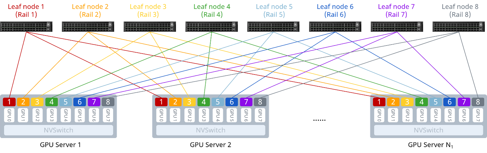
The ROFT architecture improves All-Reduce efficiency in training scenarios through rail optimization, but its design assumes that traffic is symmetric and predictable.
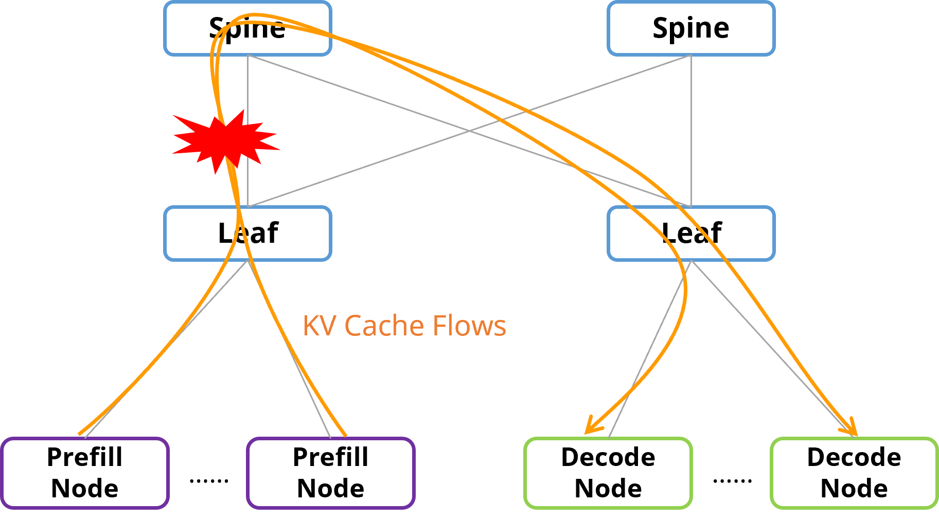 In PD disaggregation, the source-destination relationship of KV Cache transfers is determined entirely and dynamically by the scheduler. Prefill nodes may end up concentrated under a small number of leaf switches, causing the uplinks of those leaf switches to be hit disproportionately hard and creating architectural hotspots. This congestion is not caused by transient traffic bursts — it is structural congestion caused by a mismatch between the network topology and the PD-disaggregated traffic model.
2.3.3 Multi-Hop Forwarding and the Spine Bottleneck
In a traditional three-tier Clos architecture, cross-leaf traffic must traverse the spine layer (Leaf → Spine → Leaf, three hops total). In PD-disaggregated scenarios, over 90% of KV Cache transfers are cross-leaf traffic, and all of it must converge at the spine layer. Even with spine-layer oversubscription, the spine-leaf links remain an unavoidable bottleneck, and the additional hop further amplifies transfer latency.
3 Asymmetric Dual-Plane Network Architecture Design
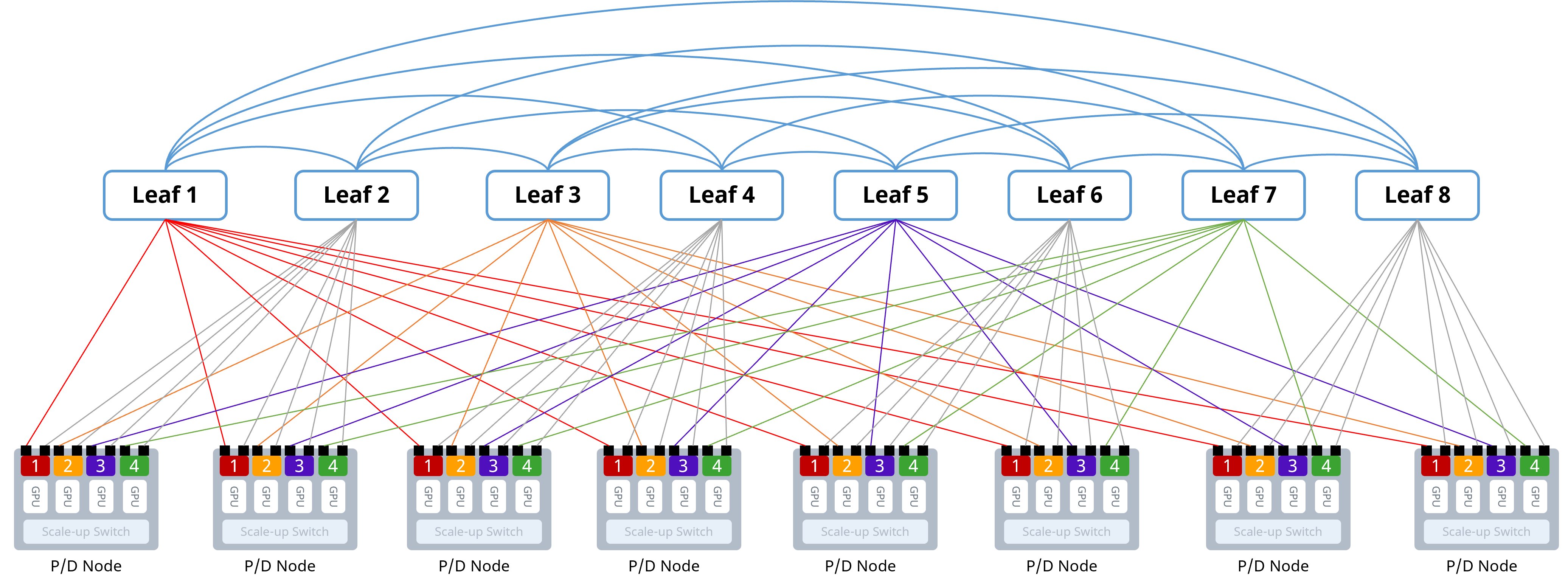 3.1 Architecture Design Philosophy
The design goal of the asymmetric dual-plane architecture is to eliminate structural congestion in PD-disaggregated scenarios at the network-topology level, rather than relying on higher-layer scheduling or more complex transport-layer protocols. Its core design principles include:
Removing the spine layer: completely eliminates the aggregation bottleneck for cross-leaf traffic, compressing the network diameter from three hops to two;
Complete bipartite-graph interconnection: leaf switches are split into two planes, with full-mesh interconnection between the two planes' leaf switches, providing the shortest, deterministic path for KV Cache transfers;
Combined single-rail and multi-rail access: through orthogonal dual partitioning, structured blocks of Prefill/Decode nodes are evenly spread across the underlying links, achieving natural load balancing;
Deterministic routing: exactly one optimal path exists between any pair of GPUs, eliminating ECMP hash collisions.
3.2 Networking Architecture
The asymmetric dual-plane architecture removes the spine tier of the traditional Fat-Tree architecture, splitting all leaf switches into two equally sized groups:
Plane A (multi-rail plane, odd-numbered leaf group): numbered 1, 3, 5, ...
Plane B (single-rail plane, even-numbered leaf group): numbered 2, 4, 6, ...
A complete bipartite full-mesh is built between the two switch groups: every switch in Group A has a direct link to every switch in Group B, while switches within the same plane have no interconnection.
Each GPU's dual-port NIC connects to the two switch groups separately:
First port (multi-rail port): connects to the odd-numbered Plane A leaf switches, following multi-rail rules
Second port (single-rail port): connects to the even-numbered Plane B leaf switches, following single-rail rules
Using a minimal network of 4 GPU servers and 4 leaf switches per group as an example, the topology and cabling relationships are as follows:
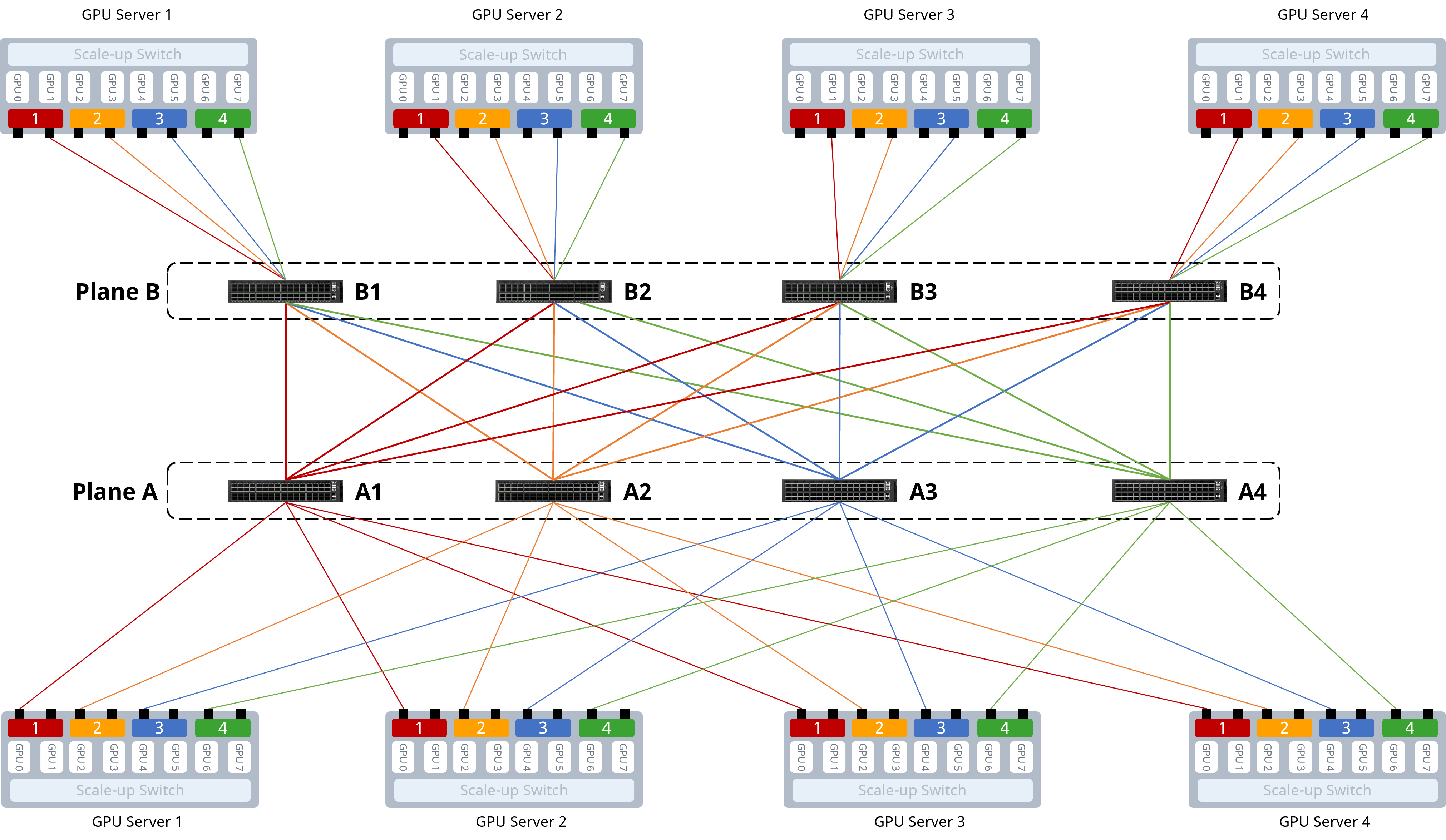 Each server's multi-rail ports connect respectively to the 4 leaf switches in Plane A; each server's single-rail ports connect respectively to the 4 leaf switches in Plane B; the two leaf groups are fully interconnected. Under this networking architecture, the forwarding path between any two GPUs on the network is always exactly two hops: GPU → local-group leaf → peer-group leaf → GPU. For PD-disaggregated scenarios, this means that a KV Cache transfer from any Prefill node to any Decode node needs to traverse only two switches — the shortest possible path, and the only one.
3.3 Traffic Paths
Forwarding paths between GPUs vary by scenario, as follows:
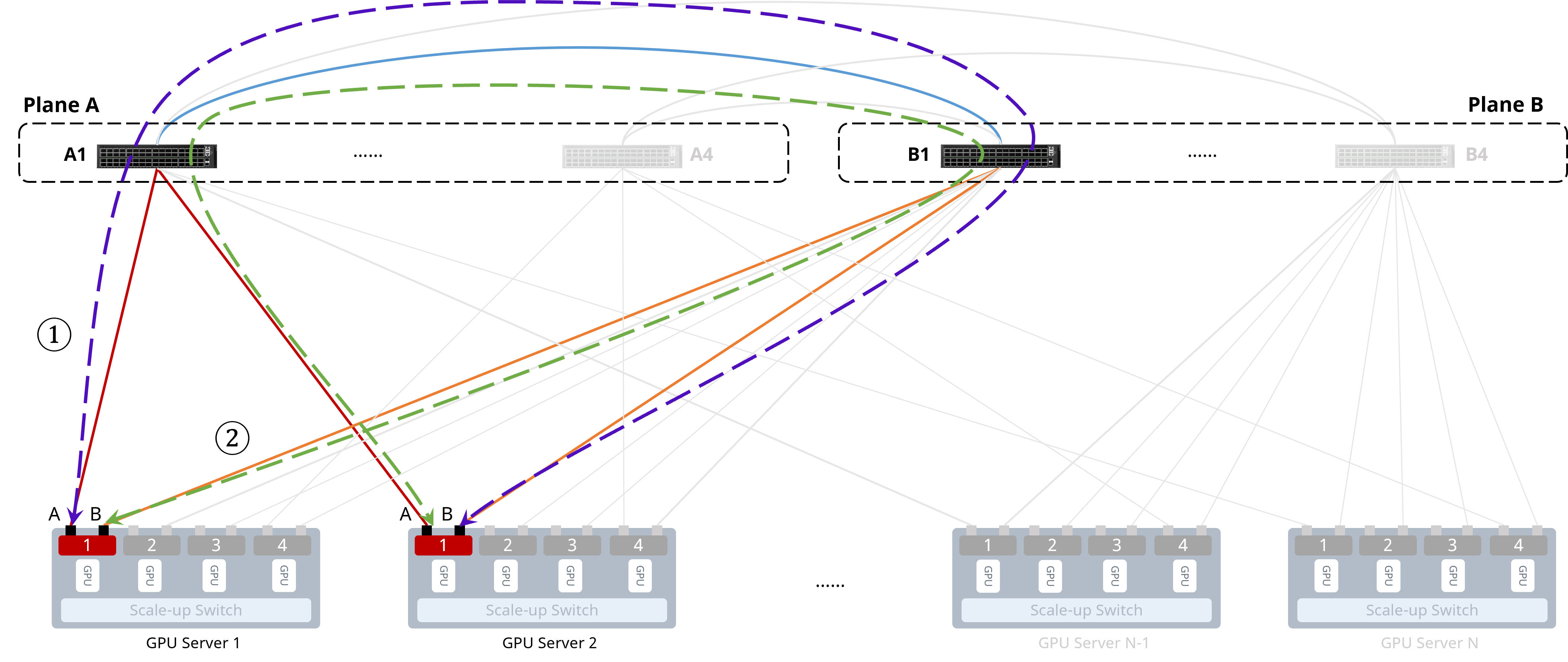
Same-rail communication
GPU 1 on Server 1 accesses GPU 1 on Server 2:
① Server 1-1-A → Leaf A1 → Leaf B1 → Server 2-1-B, forwarded in two hops
② Server 1-1-B → Leaf B1 → Leaf A1 → Server 2-1-A, forwarded in two hops
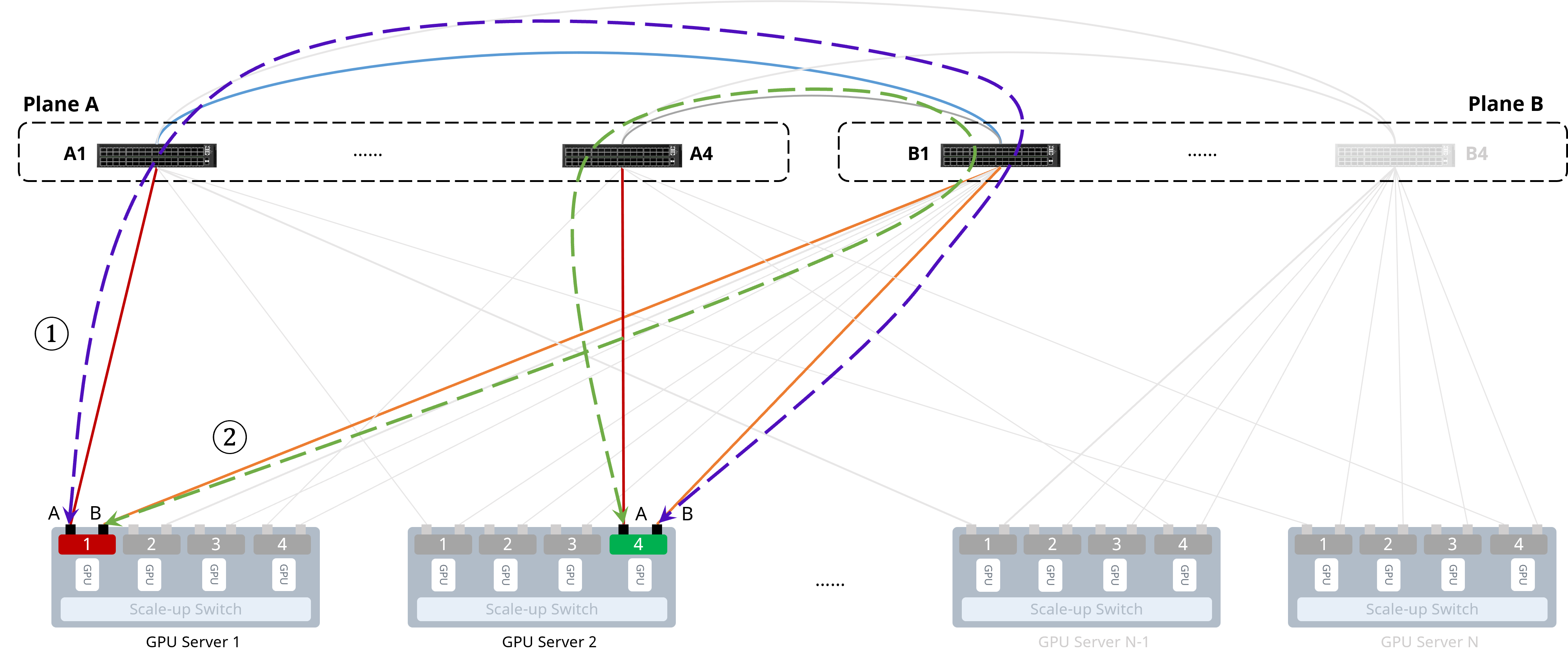
 Cross-rail communication
GPU 1 on Server 1 accesses GPU 4 on Server 2:
① Server 1-1-A → Leaf A1 → Leaf B1 → Server 2-4-B, forwarded in two hops
② Server 1-1-B → Leaf B1 → Leaf A4 → Server 2-4-A, forwarded in two hops
3.4 Key Technologies
3.4.1 Dual-Port NIC Access
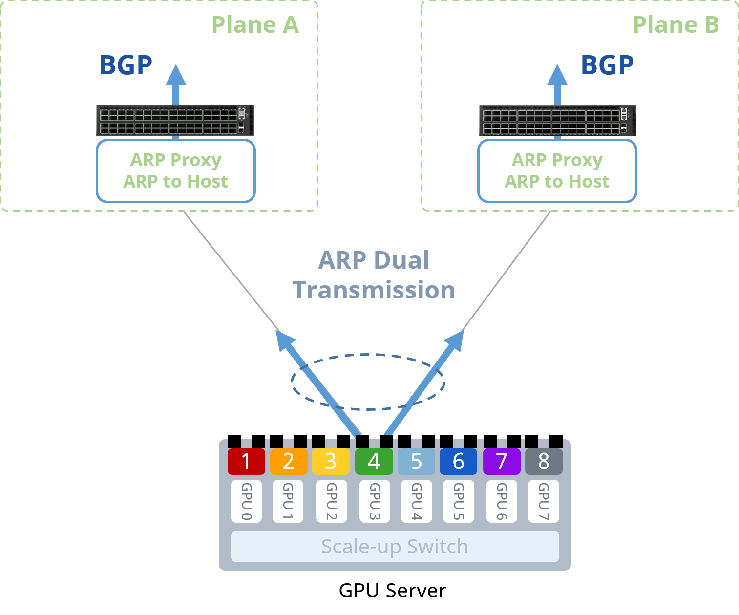
The server's NIC uses bonded dual uplinks, connecting to the leaf switches of both planes. To ensure that both leaf switches maintain consistent ARP and MAC-address learning for the server, the following mechanisms must be enabled:
Dual ARP transmission from the NIC: the server's NIC must be able to send ARP requests simultaneously out both uplink ports, so that both leaf switches learn the server's MAC and IP addresses;
ARP-to-host routing on the switches: the leaf switches enable ARP-to-host routing, converting learned ARP entries into /32 host routes and advertising them to the other plane via uplink BGP.
 3.4.2 Routing Scheme
To achieve the constant two-hop forwarding described above, single-hop routes (which would allow local-route forwarding) and multi-hop routes (which would allow traffic in Plane A to pass through Plane B and back into Plane A) must both be strictly filtered out:
Same-group leaf switches share the same AS: BGP AS-path filtering excludes routes longer than two hops, ensuring traffic is never forwarded within the same plane or routed back and forth across planes multiple times;
Unnumbered BGP neighbors via IPv6 link-local addresses: interconnect interfaces between Plane A and Plane B require no IP address planning at all — BGP neighbor sessions are established automatically using IPv6 link-local addresses, simplifying deployment;
Only host routes are advertised: through the ARP-to-host routing mechanism, each leaf switch advertises only the host routes of its directly connected GPUs, keeping the routing table lean and convergence fast.
3.4.3 Load-Balancing Technology
Traditional ECMP per-flow load balancing has a fatal weakness in PD-disaggregated scenarios: when traffic is homogeneous (e.g., dominated by large KV Cache elephant flows), the hashing algorithm can easily map multiple large flows onto the same member link, triggering congestion.
The asymmetric dual-plane architecture's load-balancing capability comes from the topology itself, not from ECMP hashing:
Natural, even distribution from the complete bipartite graph: any Plane A leaf switch is fully interconnected with every Plane B leaf switch, so traffic naturally spreads across cross-group links, with no inherent structural hotspot links;
Combined single-rail and multi-rail access: the multi-rail ports spread GPUs in the same slot position across different Plane A leaf switches, while the single-rail ports concentrate consecutively numbered GPUs onto a single Plane B leaf switch. This orthogonal dual partitioning ensures an even path distribution regardless of whether traffic is rail-aligned (training mode) or highly asymmetric in source and destination (PD-disaggregated mode).
3.5 Scale Comparison
Using a 51.2 Tbps switch and 400 Gbps of NIC bandwidth per GPU as an example, the asymmetric dual-plane architecture supports 128 GPU servers (1K GPUs) per pod, scaling up to a maximum of 16 pods — for a maximum cluster size of 16K GPUs.
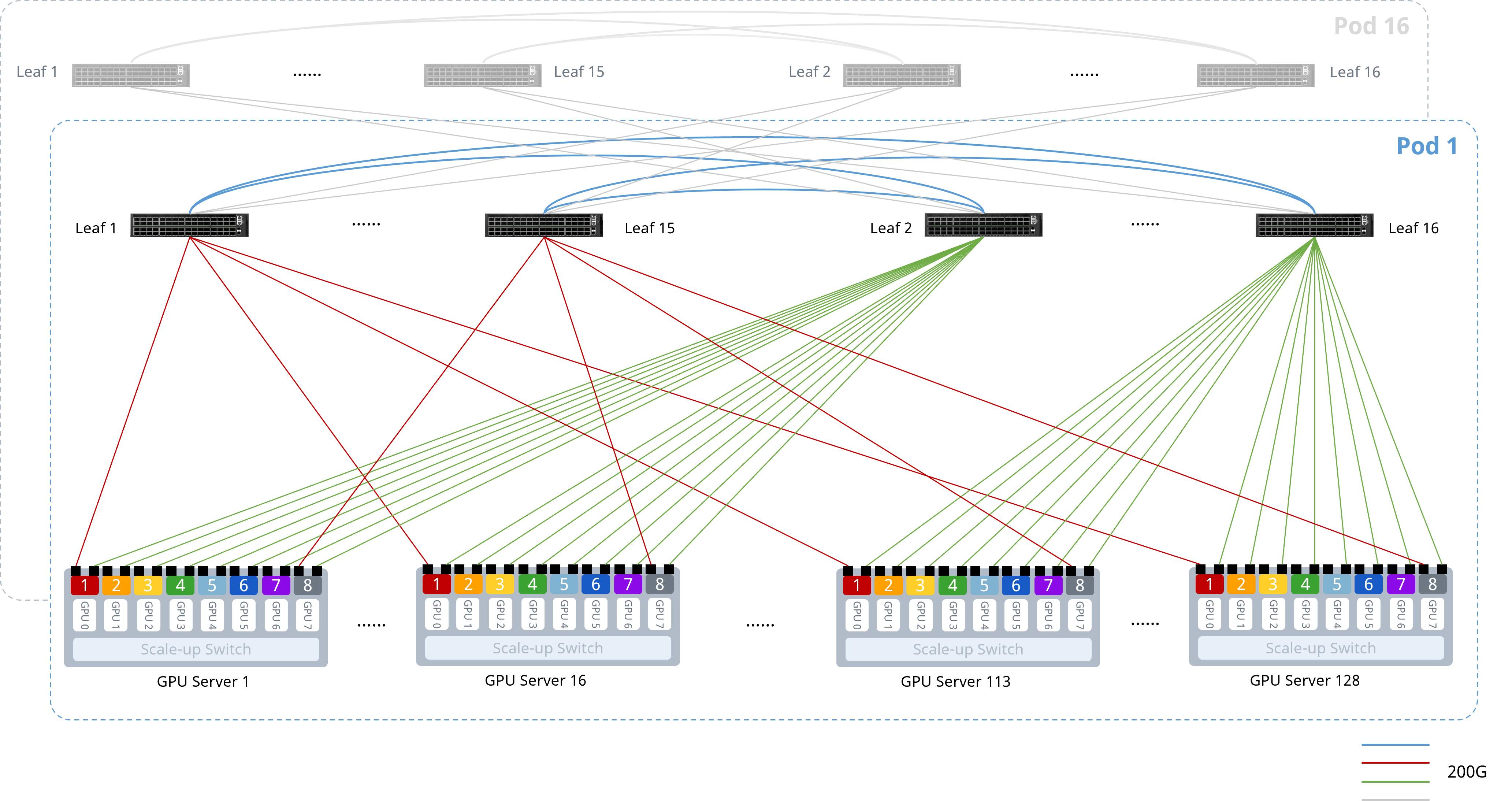 Using an 8K-GPU cluster as the baseline, the hardware configurations of three network topology options compare as follows:
Table 2 Hardware Configuration Comparison for an 8K-GPU Cluster
Topology | ROFT | Symmetric Dual-Plane | Asymmetric Dual-Plane |
|---|---|---|---|
Number of switches | 192 | 192 | 128 |
800G modules | 12,288 | 12,288 | 8,192 |
400G modules | 8,192 | — | — |
200G modules | — | 16,384 | 16,384 |
Number of cables | 12,288 | 12,288 | 10,240 |
As shown in the table above, for the same GPU cluster scale, the asymmetric dual-plane architecture reduces the switch count by 33% and hardware cost by 30%–40%, while also delivering superior transfer efficiency purpose-built for the asymmetric PD-disaggregated traffic model.
4 Building an Asymmetric Dual-Plane Network for AI Compute
4.1 Cluster Networking Design
4.1.1 Networking Scheme
The figure below shows the asymmetric dual-plane networking architecture for an AI compute cluster with 128 Prefill/Decode nodes (1,024 GPUs). Each server carries 8 GPUs, and each GPU corresponds to a dual-port 200G NIC. A total of 16 CX864E-N switches are deployed — 8 in Plane A (odd-numbered leaf nodes) and 8 in Plane B (even-numbered leaf nodes). The CX864E-N is equipped with 64 × 800GE ports, which, through port breakout, can provide 128 × 200G ports (for Leaf-Server connections) and 64 × 400G ports (for Leaf-Leaf connections).
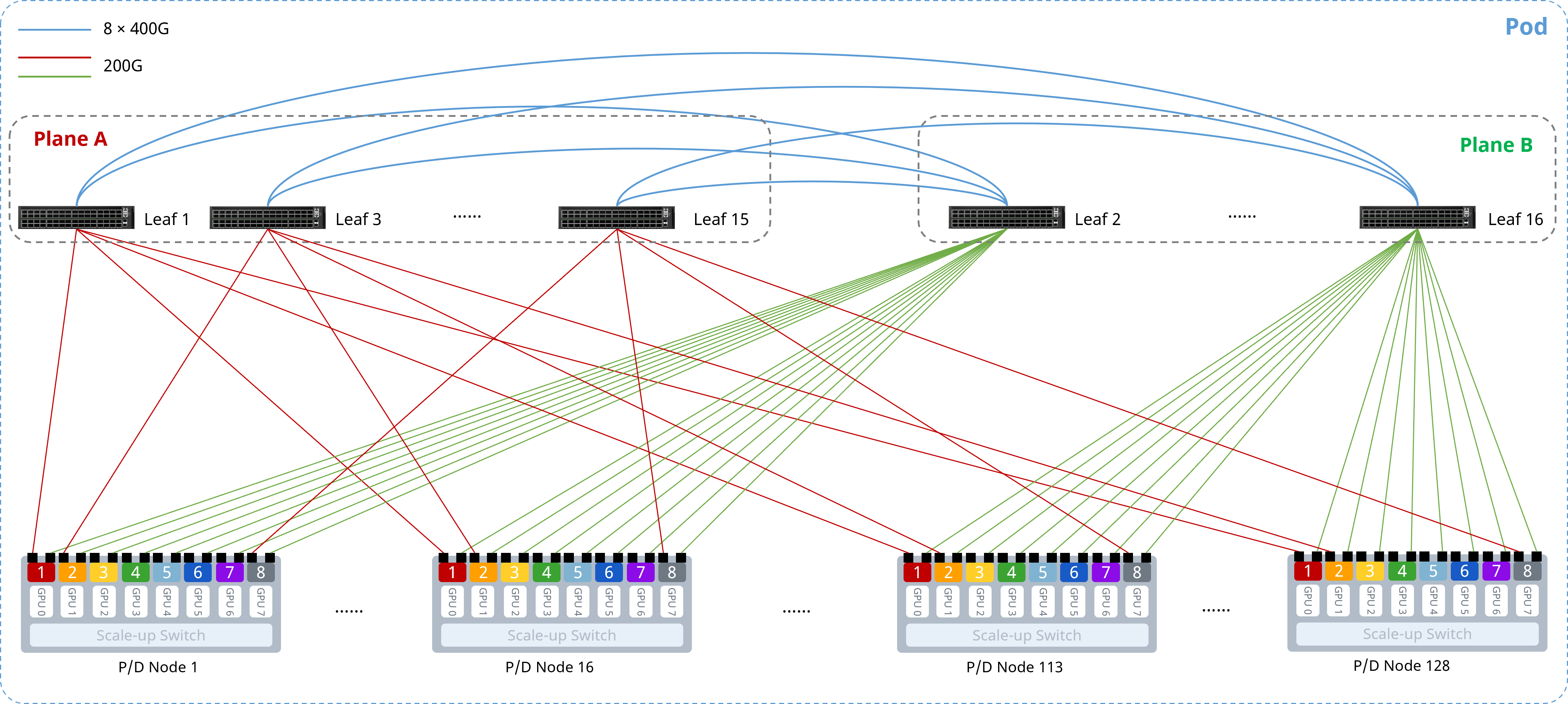 The core design principles of the asymmetric dual-plane architecture are as follows:
Each GPU connects to a dedicated 400G NIC, which breaks out into two 200G ports connecting to the two planes respectively. Server-side port connections strictly follow this pattern: the first port of each server's NIC connects to the Plane A (odd-numbered) leaf switches following the rule "NIC1 port 1 → Leaf 1, NIC2 port 1 → Leaf 3, NIC3 port 1 → Leaf 5, ..."; the second port connects sequentially to the Plane B (even-numbered) leaf switches.
Each plane's network has only a single leaf tier, with no interconnection links between leaf switches within the same plane; Plane A and Plane B leaf switches are fully interconnected (full-mesh) and use IPv6 link-local addresses to establish unnumbered BGP neighbor sessions, advertising each plane's host routes to enable route exchange — with no need to plan IP addresses for the inter-plane interconnect interfaces.
The ratio between a leaf switch's downlink and uplink capacity must strictly follow a 1:1 convergence ratio to guarantee non-blocking transport.
All switches enable one-click RoCE and load-balancing features to build a lossless network.
4.1.2 Device Selection
For building medium-to-large-scale RoCEv2 networks, the CX864E-N data center switch is recommended, thanks to its ultra-low forwarding latency — the CX864E-N delivers end-to-end forwarding latency as low as 560 ns, achieving ultra-low-latency data transport that fully satisfies RoCEv2's stringent latency requirements. Because the asymmetric dual-plane architecture removes the spine layer, leaf switches take on both access and interconnect roles simultaneously; every node within a single pod is deployed with the same switch model, simplifying spare-parts management for operations.
In an asymmetric dual-plane network, using the NVIDIA DGX H100 GPU server (8 GPUs per server) as an example, a single pod requires 16 leaf nodes — 8 per plane. The maximum number of servers a pod can support is determined by the leaf node's port configuration. To maintain a 1:1 convergence ratio, half of each leaf node's ports connect to GPU servers, and the other half connect to leaf switches on the opposite plane.
The table below shows the node configuration requirements for deploying asymmetric dual-plane networks of various GPU counts using the CX864E-N:
Table 3 Node Configuration Requirements for Asymmetric Dual-Plane Networks of Various GPU Counts, Using the CX864E-N
Total GPUs / Servers | Plane A Nodes | Plane B Nodes | 200G Links Between Plane A and B | Total Nodes |
|---|---|---|---|---|
512 / 64 | 4 | 4 | 32 | 8 |
1,024 / 128 | 8 | 8 | 16 | 16 |
2,048 / 256 | 16 | 16 | 8 | 32 |
4,096 / 512 | 32 | 32 | 4 | 64 |
8,192 / 1,024 | 64 | 64 | 2 | 128 |
16,384 / 2,048 | 128 | 128 | 1 | 256 |
5 Conclusion
As large-model inference evolves from a "unified training-and-inference" model toward a dedicated PD-disaggregated architecture, the underlying network is undergoing a paradigm shift from "general-purpose symmetric topologies" to "inference-specific asymmetric topologies." The asymmetric dual-plane architecture proposed in this solution — through removing the spine layer, building a complete bipartite graph, combining single-rail and multi-rail access, and applying deterministic routing — eliminates structural congestion in PD-disaggregated scenarios at the network-topology level, providing a complete solution for large-scale, inference-dedicated GPU clusters.