
Abstract
As traffic analysis deployments grow more complex, directly connecting backend analysis tools to an NPB (Network Packet Broker) is often impractical. This article covers the rationale, core advantages, working principles, Web-UI configuration process, packet-level behavior, and planned enhancements for GRE and VXLAN tunnel encapsulation on NPB.
1. Background: Two Deployment Models
1.1 Direct-Attach Deployment
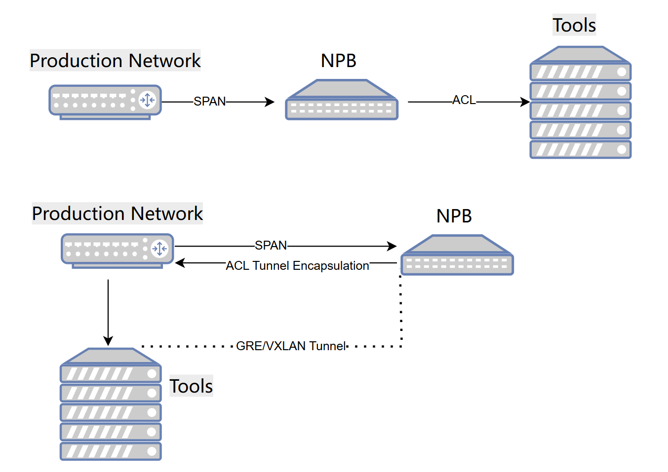
In conventional deployments, NPB connects to analysis tools via fiber. Mirrored traffic reaches NPB through SPAN, is processed against ACL rules, and is forwarded directly to ports connected to analysis tools.
This model has two constraints: analysis tools must be physically located near the NPB, and both cabling and port availability limit scalability.
1.2 Tunnel-Encapsulated Deployment
In a tunnel-based deployment, NPB no longer connects directly to analysis tools. Instead, it uplinks to production switches, and mirrored traffic is encapsulated into GRE or VXLAN tunnels before being forwarded across the existing Layer 2/Layer 3 IP network to remote analysis tools.
This allows analysis tools to be deployed anywhere with Layer-3 reachability, independent of physical cabling.
2. Core Advantages of NPB Tunnel Encapsulation
2.1 Reduced Cabling and Port Consumption
Direct-attach deployments require a dedicated fiber connection per analysis tool, leading to dense cabling and frequent rewiring whenever tools are relocated. Physical ports on the NPB are also consumed quickly.
With tunnel encapsulation, NPB requires only one or two uplink ports to the production network. All mirrored traffic is carried over GRE/VXLAN, and adding, removing, or relocating analysis tools requires no physical rewiring.
2.2 Reuse of Existing Layer-3 Infrastructure
The existing production IP network can serve as the transport layer, removing the need for additional switches or fiber and reducing capital expenditure.
2.3 Support for Distributed Collection Architectures
This approach fits distributed collection scenarios—for example, signaling analysis across a railway network—where each site runs an NPB collector, and all collectors forward traffic to a centralized analysis platform over GRE/VXLAN tunnels across the Layer-3 network.
This model assumes Layer-3 reachability between NPB and analysis tools, and is best suited to lower-traffic workloads.
3. Working Principle
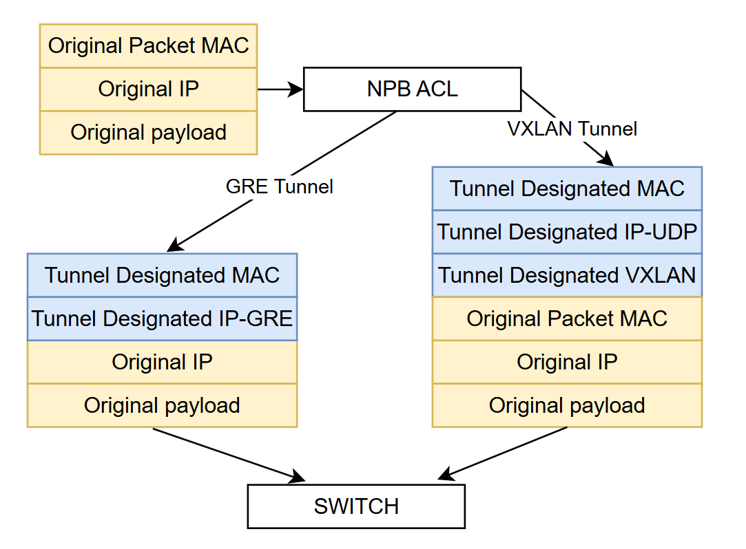
NPB receives the original mirrored packet, including its MAC header, IP header, and payload. Traffic matching an ACL forwarding policy can be bound to a GRE or VXLAN tunnel instance.
Tunnel parameters—source/destination MAC, tunnel source/destination IP, DSCP, VNI (for VXLAN), and UDP port—are configured in advance.
When a packet matches a policy bound to a tunnel, NPB adds the following headers:
GRE tunnel: Outer Ethernet header + Outer IP header + GRE header, with the entire original packet carried as GRE payload.
VXLAN tunnel: Outer Ethernet header + Outer IP header + UDP header + VXLAN header, with the original Layer-2 frame carried as VXLAN payload.
The encapsulated packet exits through the NPB uplink port and is routed by the switching infrastructure to the remote analysis tool.
4. Web-UI Configuration Guide
Navigation path: Forwarding Policy → Global Config → Tunnel Header
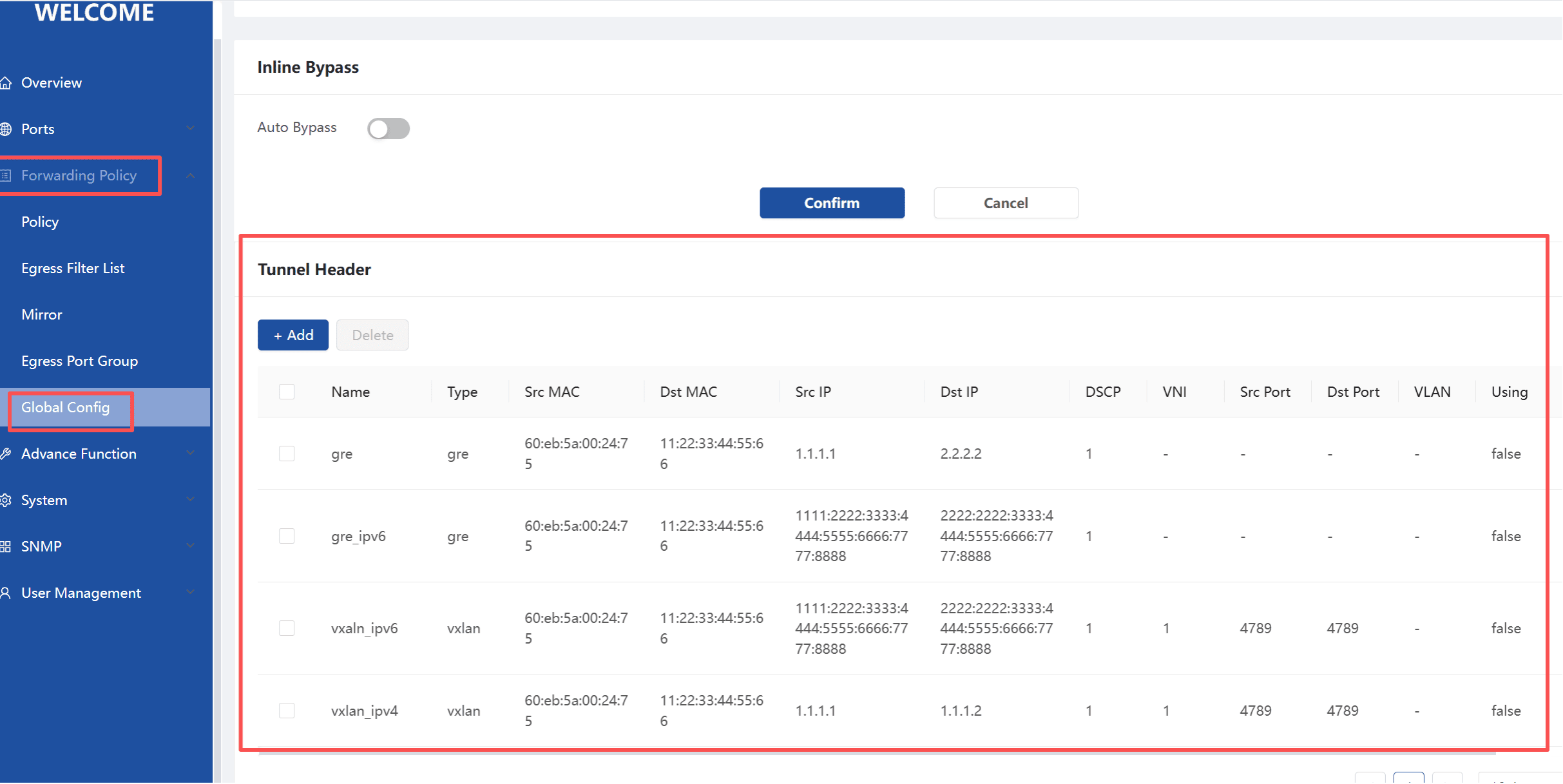
4.1 Creating a Tunnel Instance
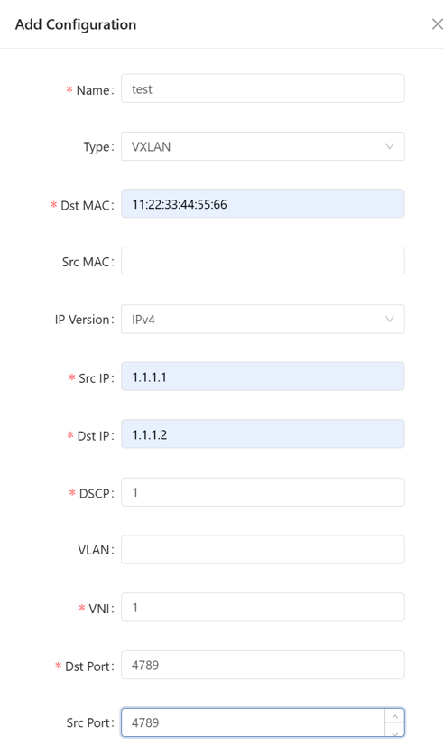
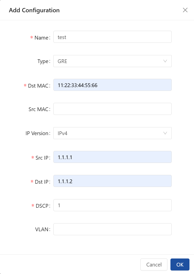
On the Tunnel Header page, click Add and configure the following:
Name: Custom identifier for the tunnel
Type: GRE or VXLAN
IP Version: IPv4 or IPv6
Dst MAC: Peer device MAC address (required)
Src MAC: Defaults to the NPB system MAC; editable
Src IP / Dst IP: Tunnel endpoint addresses
DSCP: DSCP marking for outer IP packets
VLAN (optional): Outer VLAN tag for tunnel packets
VNI (VXLAN only): VXLAN network identifier
Src Port / Dst Port (VXLAN only): Standard destination port is 4789
Save to complete tunnel creation.
|
|
Constraints: Existing tunnel configurations cannot be edited in place—parameter changes require deleting and recreating the tunnel. A tunnel must be unbound from any forwarding policy before it can be deleted.
4.2 Binding a Tunnel to a Forwarding Policy
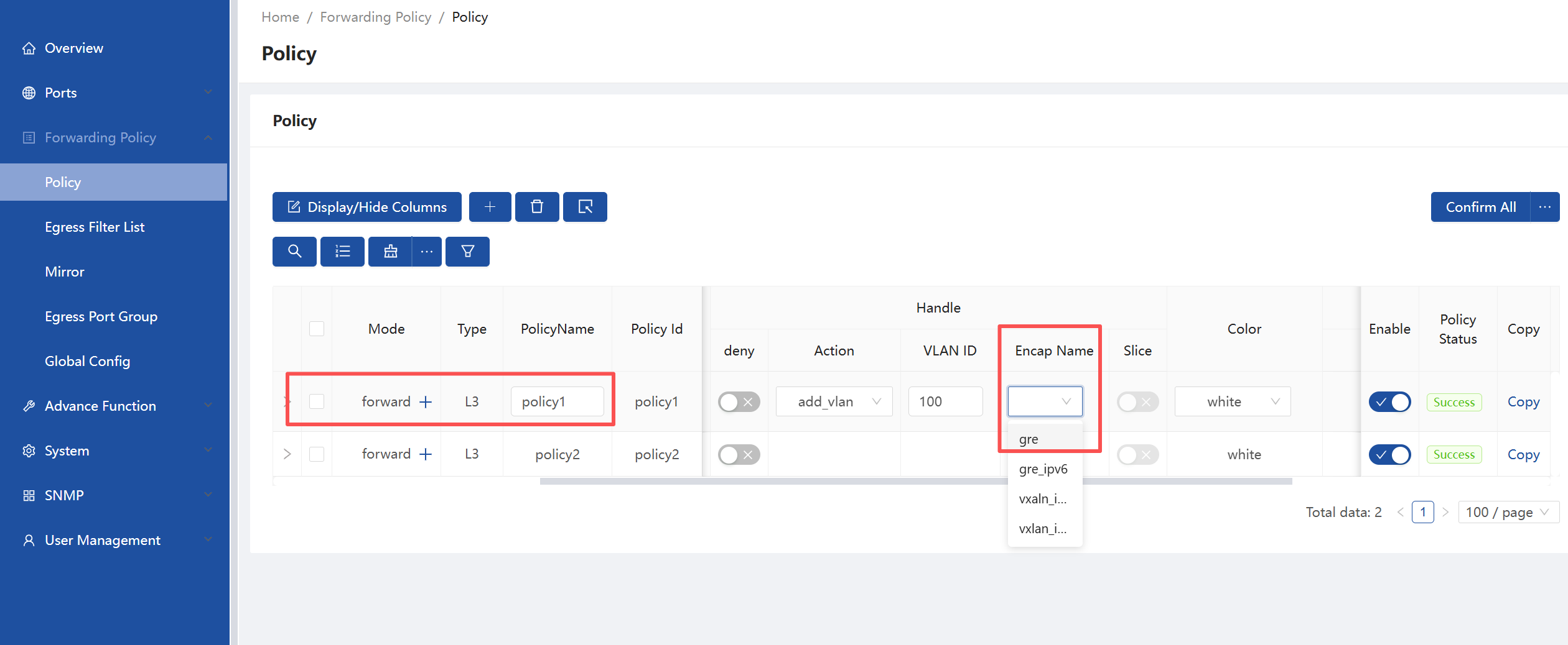
Navigate to Forwarding Policy → Policy.
Create or edit a policy.
In the policy setting Encap Name, select the pre-created tunnel instance from the dropdown list.
Save the policy.
5. Packet-Level Results
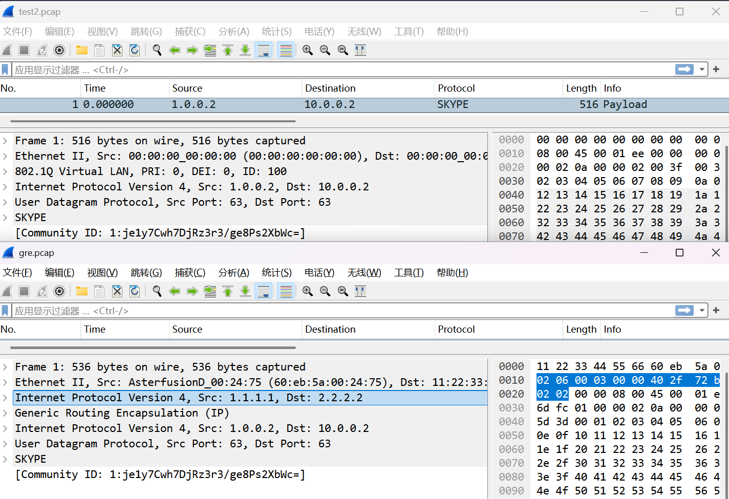
Comparing original and encapsulated packets in Wireshark:
GRE Encapsulation: Original (Ethernet → VLAN → IP → UDP → payload) becomes Outer Ethernet → Outer IP → GRE header → complete original packet.
VXLAN Encapsulation: Becomes Outer Ethernet → Outer IP → UDP (4789) → VXLAN header → complete original Layer-2 frame.
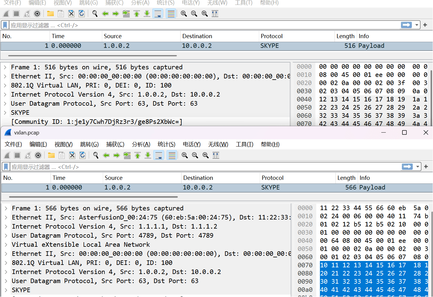
In both cases, the original user-plane payload is preserved unchanged within the tunnel.
6. Roadmap
The current release requires manual configuration of the destination MAC. Planned enhancements include:
Next-hop IP-based configuration with automatic MAC resolution via ARP
Fragmentation handling for tunnel-encapsulated packets exceeding MTU
Load balancing across multiple tunnel instances under a single forwarding policy
NVGRE tunnel support
7. Conclusion
GRE/VXLAN tunnel encapsulation shifts NPB traffic distribution from physical direct-attach connections to IP-tunnel-based forwarding. It addresses deployment-location constraints, cabling complexity, and port exhaustion, while reusing existing Layer-3 infrastructure to lower deployment costs. The approach is particularly applicable to distributed, multi-site collection with centralized analysis.
Configuration is performed through the Web-UI by creating tunnel instances and binding them to forwarding policies. Future releases are expected to add fragmentation handling, load balancing, and NVGRE support.