
I. Solution Background and Pain Points of Traditional DCI Architectures
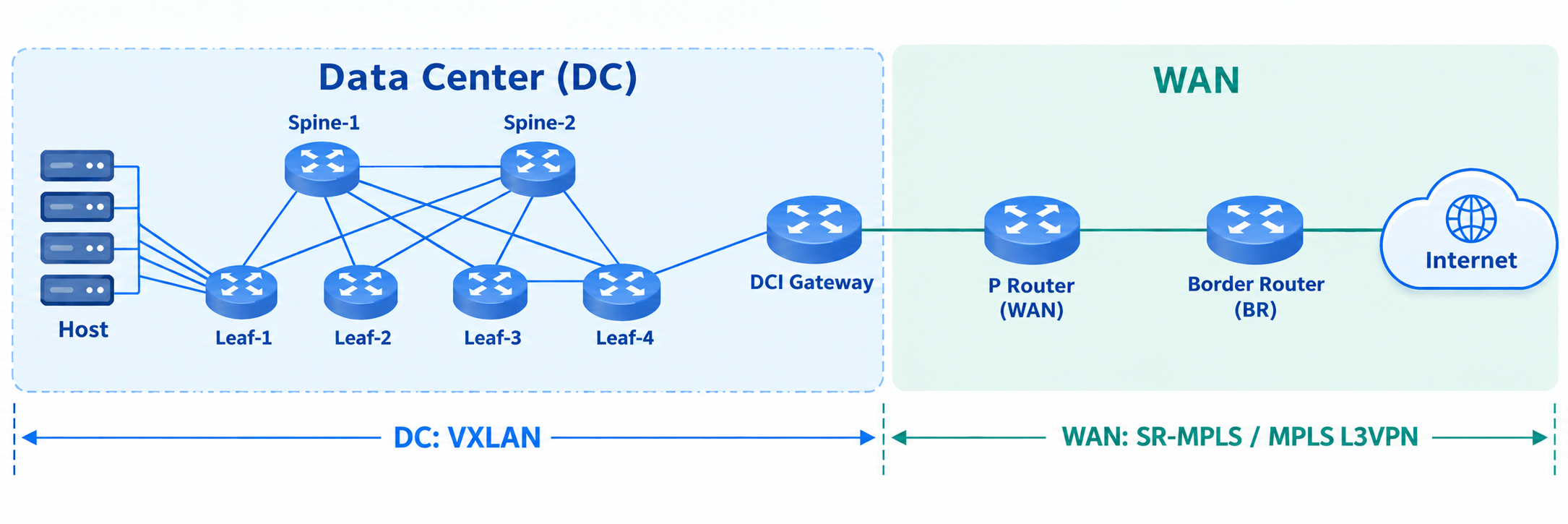
In traditional enterprise and cloud-provider networks, the data center (DC) internal network (typically built on a VXLAN overlay) and the external wide-area network (WAN, typically built on SR-MPLS or MPLS L3VPN) are split into mutually isolated technology silos. This "fragmented" architecture faces severe technical bottlenecks in the era of cloud-native computing and AI compute:
DCI (Data Center Interconnect) Gateway Bottlenecks & High Cost: DCI gateways must perform complex bidirectional protocol translation (VXLAN ⇔ SR-MPLS / MPLS L3VPN). Maintaining network-wide VRF routing states turns the gateway into a single point of failure and scalability limit.
Loss of Metadata & Tenant Context: Security policy tags, network-slice IDs, and QoS parameters are stripped or lost across protocol-translation boundaries.
Rigid Service Function Chain (SFC) Insertion: Inserting firewalls or IPS requires complex Policy-Based Routing (PBR) or traffic-steering VRFs, forcing security appliances into centralized "mega-clusters" that cannot scale horizontally.
Heavy Header Overhead (MTU Tax): Stacking VXLAN (50 bytes) and MPLS label stacks increases fragmentation risks and reduces payload efficiency.
To resolve these pain points, AsterNOS delivers full-stack support for SRv6 DCI cross-domain architectures across Option A, Option B, and Option C, empowering enterprises and carriers to construct highly resilient, pure IPv6 cloud-network convergence infrastructures.
II. In-Depth Walkthrough of AsterNOS's Three SRv6 DCI Cross-Domain Mechanisms
1. Option A: Segment-by-Segment VRF Stitching (Service Termination Mode)
Core Approach
Gateway Role: ASBRs act as CEs to each other. Cross-domain VPN routes are downgraded to ordinary IPv4/IPv6 unicast routes exchanged over ordinary EBGP sessions.
Trade-offs: Simple to implement with zero cross-domain signaling dependencies. However, scalability is poor: ASBRs must maintain full tenant VRF sets and allocate dedicated physical/sub-interfaces per tenant, causing table-size explosion.
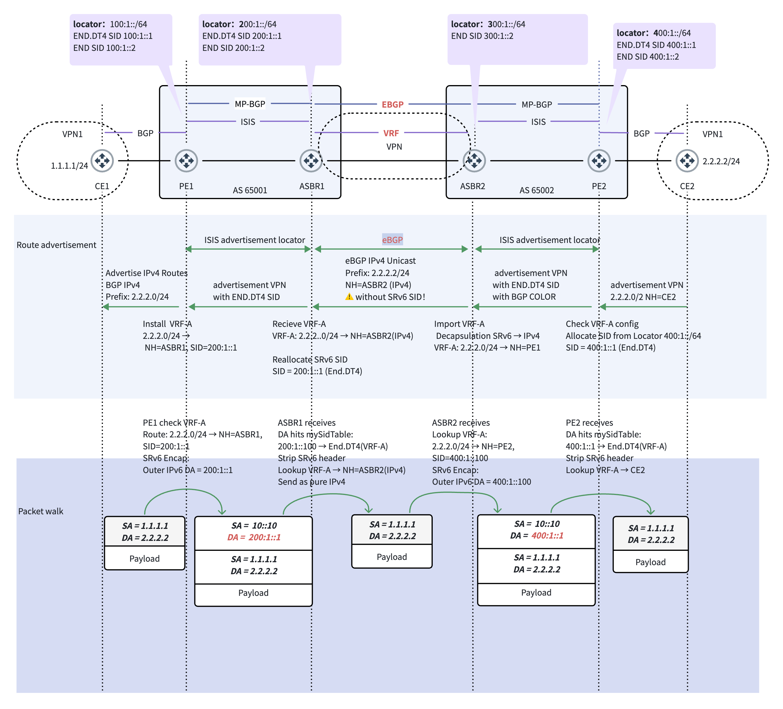
Packet-Forwarding Flow (CE 1 accessing CE 2)
CE 1 $\rightarrow$ PE 1: Sends a native IPv4 packet.
PE 1 Encapsulation: PE 1 looks up VPN instance A, matches the End.DT4 SID (
200:1::1) of ASBR 1, and encapsulates the packet into an outer IPv6 header.Forwarding in AS 1: Routed via global IPv6 IGP to ASBR 1.
ASBR 1 Termination: ASBR 1 matches the End.DT4 instruction, strips the outer IPv6 header, looks up the inner packet in tenant VRF A, and forwards a bare IPv4 packet across the domain link to ASBR 2.
ASBR 2 Re-encapsulation: ASBR 2 receives the bare IPv4 packet on the VRF-bound sub-interface, looks up VRF A, and re-encapsulates it with a new outer IPv6 header pointing to PE 2's End.DT4 SID (
400:1::1).PE 2 Termination: PE 2 receives the packet, matches End.DT4, strips the outer header, and delivers the original IPv4 packet to CE 2.
2. Option B: Relay Lookup and SID Rewrite Mode (Relay SID & Transit Rewrite)
Core Approach
Underlay Isolation: Locator routes are kept internal to each domain and never leaked across AS boundaries.
Control & Data Plane: ASBRs maintain a global BGP VPNv4 table (no tenant VRFs). They allocate a local relay SID (End.T) via MP-EBGP. Upon receiving a packet, the ASBR does not decapsulate the inner IP—it rewrites the outer IPv6 DA in-place (SID Swap) in hardware.
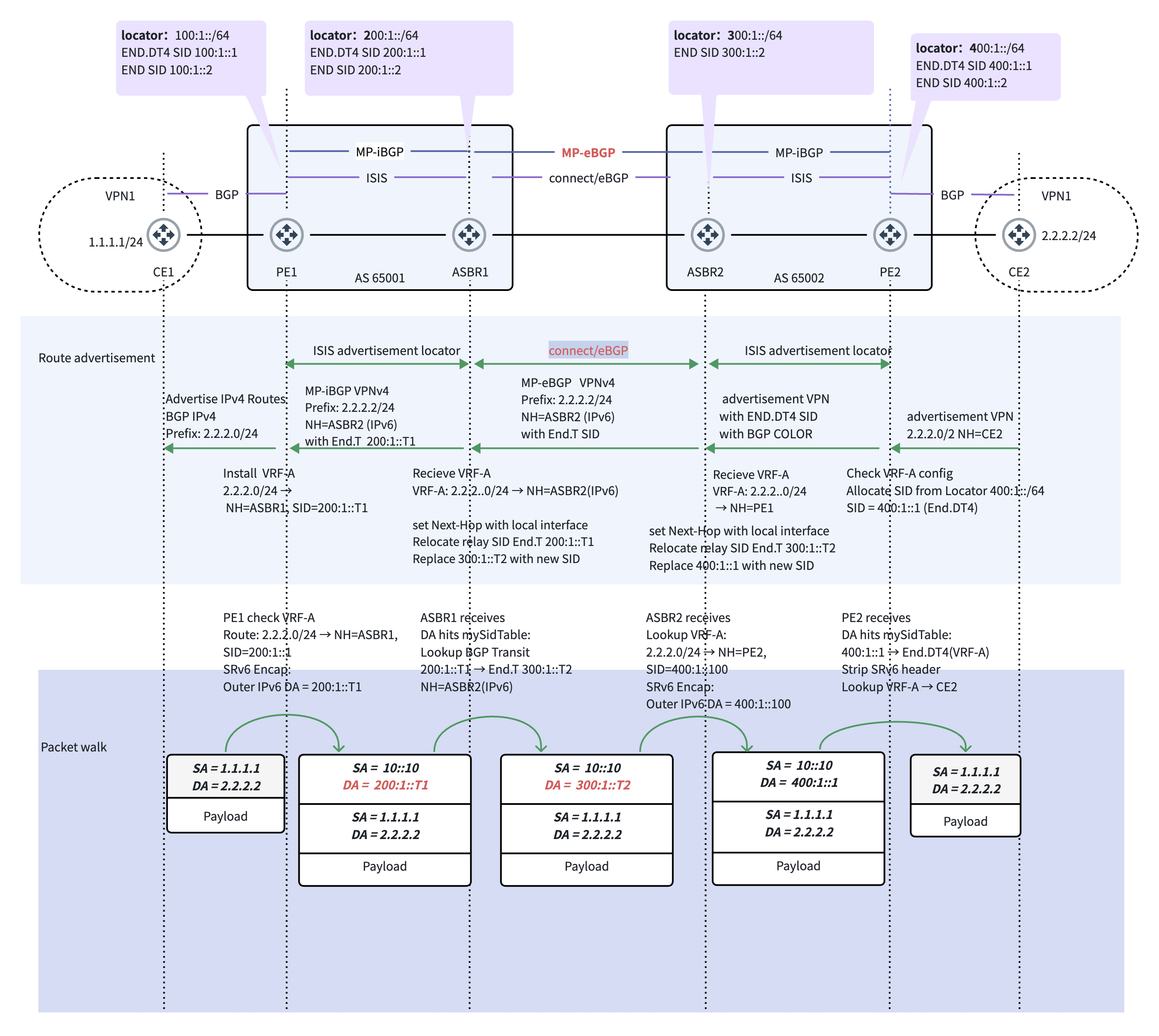
Packet-Forwarding Flow (CE 1 accessing CE 2)
PE 1 Encapsulation: PE 1 encapsulates the payload with outer IPv6 DA set to ASBR 1's Relay SID (
200:1::T1).ASBR 1 First SID Swap: ASBR 1 matches
End.T 200:1::T1. Without decapsulating, it looks up the BGP Transit table, rewrites the IPv6 DA to ASBR 2's Relay SID (300:1::T2), and forwards it across the boundary.ASBR 2 Second SID Swap: ASBR 2 matches
End.T 300:1::T2, looks up the Transit table, rewrites the IPv6 DA to PE 2's End.DT4 SID (400:1::1), and forwards it into AS 2.PE 2 Termination: PE 2 receives the packet (
400:1::1), strips the outer IPv6 header, and delivers the bare IPv4 payload to CE 2.
3. Option C: End-to-End Seamless SRv6 Mode
Core Approach
Underlay Interconnection: PE Locator prefixes are advertised network-wide across domains.
Stateless ASBRs: PEs establish direct multi-hop MP-EBGP sessions (or via RRs). ASBRs maintain no tenant VRFs, allocate no SIDs, and perform no SID rewrites—they function as pure, stateless IPv6 LPM forwarders.
Single-Pass Data Plane: Ingress PE directly encapsulates the peer PE's target business SID. The packet travels end-to-end with zero decapsulation and zero SID swaps along the path.
Hardware Optimization: uSID (NEXT-C-SID, RFC 9352)
To eliminate the legacy SRv6 "MTU tax" caused by bulky Segment Routing Headers (SRH), AsterNOS natively supports uSID (Micro-Segment). By encoding multiple 16-bit Micro-SIDs within a single standard 128-bit IPv6 Destination Address (e.g., 2001:db8:1:1111:2222:3333::), AsterNOS achieves Option C traffic steering with zero SRH overhead for up to 6 hops, saving 64+ bytes per packet and guaranteeing line-rate forwarding across commodity switching silicon.
III. AsterNOS Three-Mode Comparison Matrix and Selection Guide
Complete SRv6 DCI Cross-Domain Feature Matrix
Evaluation Dimension | Option A (Layered VRF Stitching) | Option B (SID Relay Rewrite) | Option C (End-to-End Seamless) |
ASBR Control-Plane State | Extremely Heavy: Must maintain full tenant set and individual VRFs. | Moderate: Maintains global BGP Transit table; unaware of tenant VRFs. | Stateless: Zero VRFs and zero SID state on ASBRs. |
Signaling Interaction | ASBRs act as CEs, running ordinary EBGP over sub-interfaces. | ASBRs establish single-hop MP-EBGP, allocating End.T relay SIDs. | PEs establish direct multi-hop MP-EBGP (or via RRs). |
Underlay Isolation | Complete: Domain Locators are completely hidden. | Logical: Only ASBR Locators are exposed. | None: PE Locator prefixes must be reachable network-wide. |
Data-Plane Behavior | Hop-by-hop decap to bare IP; re-encapsulated after VRF lookup. | Outer IPv6 preserved; boundary nodes execute in-place SID Swap. | Single Encapsulation: Pure outer IPv6 DA LPM forwarding network-wide. |
Packet Overhead & Latency | Two rounds of decap/encap; highest latency and MTU tax. | In-place DA rewrite; lower overhead. | Lowest: Single encap + uSID compression; zero jitter. |
End-to-End SFC & Slicing | Not Supported (Slice IDs/Tags lost during decapsulation). | Supported (Requires policy mapping at boundaries). | Native Full Support: End-to-end SFC and network slicing. |
Architecture Selection Decision Matrix
Prioritize Option C for: Greenfield Pure-IPv6 DCs, AI Compute Clusters & Ultra-Low Latency Fabrics
Why: ASBRs are reduced to pure L3 IPv6 forwarders. Eliminates gateway jitter, delivering deterministic microsecond-level latency for AI All-to-All workloads.
Prioritize Option B for: Inter-Carrier Interconnection (Inter-AS), Multi-Tenant Cloud Backbones
Why: Balances scale and isolation. Avoids VRF state explosion while concealing internal PE topology from external domains.
Prioritize Option A for: Migration of Heterogeneous Networks & Strict Compliance Leased Lines
Why: Complete physical and logical decoupling. Ideal for legacy-to-SRv6 migration or environments requiring plaintext packet inspection at domain boundaries.
IV. Representative Industry Deployment Cases
1. Alibaba eCore: Option A-Style Segmented Stitching
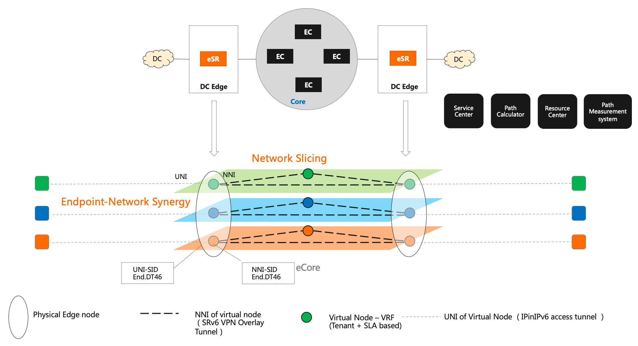
Alibaba's eCore architecture utilizes eSR edge nodes to connect UNI access tunnels with NNI WAN overlay tunnels. The data plane decapsulates incoming packets into local Virtual Node VRFs and re-encapsulates them into SRv6 WAN headers. This "decap $\rightarrow$ VRF lookup $\rightarrow$ encap" workflow demonstrates the classic Option A service termination model.
2. Nebius: Option C-Style Seamless Cross-Domain
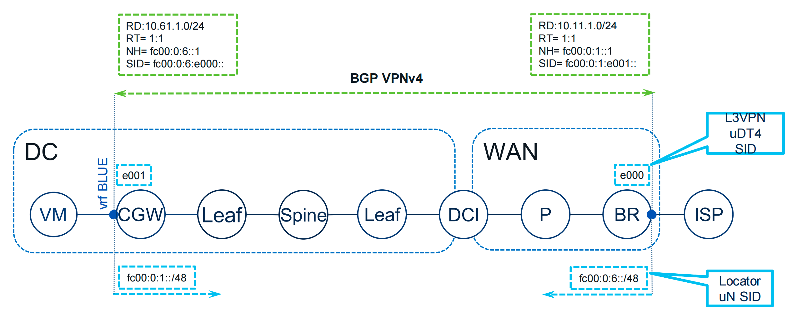
Nebius's AI DCI Fabric establishes direct BGP VPNv4 sessions between DC Gateways (CGW) and WAN Border Routers (BR). Intermediate DCI leaf/spine nodes perform pure IPv6 LPM forwarding based on outer SIDs without maintaining tenant VRFs or modifying headers. This represents a pure Option C end-to-end stateless deployment.
V. Differentiated Services & Traffic Engineering
Entropy Injection for ECMP Load Balancing: Ingress PEs extract the inner 5-tuple, calculate a 20-bit hash, and inject it into the outer IPv6
Flow Labelfield. Transit nodes achieve line-rate, per-flow ECMP load balancing based on{IPv6 SA, IPv6 DA, Flow Label}without deep packet inspection.Flex-Algo & SRv6 TE Policy: Orchestrates paths dynamically using
{Headend, Color, Endpoint}. Flex-Algo partitions the topology into SLA-driven slices (latency, bandwidth, affinity).Sub-50ms Self-Healing (TI-LFA & Fast Reroute): TI-LFA pre-computes backup segment lists for sub-50ms local link protection. Hot-Standby VPN FRR and BE fallback mechanisms guarantee uninterrupted cross-domain availability.
VI. Evolution Roadmap
AsterNOS supports a seamless, non-disruptive migration path:
Short-Term: Deploy Option A / Option B to protect legacy investments, isolate topologies, and establish secure boundaries.
Long-Term: Upgrade to Option C + uSID (RFC 9352) as the WAN matures, achieving pure stateless forwarding, sub-microsecond latency, and unified BGP-SRv6 automation across cloud-network infrastructure.