
Over the past decade of cloud evolution, EVPN-VXLAN served as the standard foundation for data center virtualization and multi-tenancy. It broke the 4,096 VLAN isolation limit, building a seamless Layer 2 Overlay network over a Layer 3 physical Underlay.
However, with the explosion of distributed Large Language Model (LLM) training, high-density GPU clusters, and cross-data-center collaborative computing, network traffic profiles have fundamentally changed. The legacy VXLAN architecture now reveals structural bottlenecks when handling massive elephant flows, cross-domain protocol translation, and encapsulation overhead. Native IPv6-based Segment Routing (SRv6) is rapidly transitioning from WAN backbones into the data center core, becoming the foundation for next-generation compute Fabrics.
1. Why Is VxLAN Struggling to Keep Up in the AI and Multi-Cloud Era?
While VXLAN effectively addressed multi-tenant isolation for virtual machines and containers in general cloud environments, its limitations become clear as infrastructure evolves toward heterogeneous compute and multi-center orchestration:
1.1 Cross-Domain "Protocol Stitching" and Gateway Bottlenecks
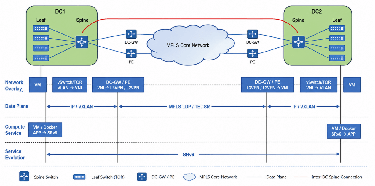
In Multi-Data-Center (DCI) or hybrid cloud topologies, EVPN-VXLAN typically handles intra-DC traffic, while MPLS, SR-MPLS, or pure IP routing runs across the WAN backbone.
State Overhead & Single-Point Bottlenecks: Data Center Interconnect (DCI) or Border Leaf gateways must manage complex protocol translation and state maintenance—decapsulating VXLAN, stripping inner labels, querying routing tables, and re-encapsulation into MPLS/WAN packets.
Operational Fragmentation: Intra-DC and inter-DC networks utilize disjointed OAM monitoring mechanisms, making end-to-end fault boundary isolation and performance telemetry extremely difficult.
1.2 Compute "Elephant Flows," ECMP Polarization, and Congestion
AI compute clusters (e.g., LLM pre-training and fine-tuning) rely heavily on large-scale collective communications (AllReduce, All-to-All). This traffic profile features low flow counts but massive, bursty single-flow throughput (elephant flows).
Hash Collisions: Traditional data centers rely on Equal-Cost Multi-Path (ECMP) routing for load distribution. Because VXLAN relies on outer UDP source ports for hashing, bursty elephant flows frequently hash to the same physical link, causing severe localized congestion.
PFC Storms & Reduced MFU: In RoCEv2 lossless networks, link congestion triggers Priority Flow Control (PFC) backpressure. This can cause PFC deadlocks or excessive queuing latency, ultimately degrading Model FLOPs Utilization (MFU) across the compute cluster. VXLAN lacks flexible Traffic Engineering (TE) capabilities to dynamically re-route around congestion.
1.3 Encapsulation Overhead and ASIC Pipeline Parsing Costs
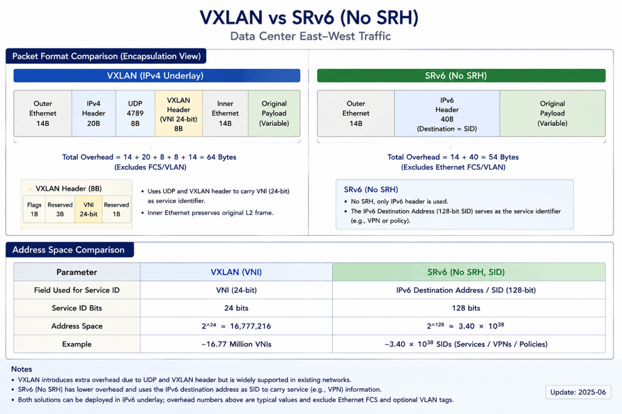
Standard VXLAN adds at least 50 bytes of encapsulation overhead (Outer MAC + IPv4 + UDP + VXLAN Header). During gradient synchronization and frequent small-parameter exchanges in AI workloads, this overhead reduces payload efficiency and places extra load on switch ASIC parsing depth and lookup pipelines.
2. Technical Principles of Next-Generation SRv6 Fabric
SRv6 is not merely a tunneling protocol; it is a network-programmable instruction set built on source routing principles and native IPv6 extension headers.
Core Dimension | EVPN-VXLAN Architecture | Next-Gen SRv6 Fabric Architecture |
Data Plane | IPv4/IPv6 Underlay + UDP Encapsulation + VXLAN Header | Native IPv6 + Routing Extension Header (SRH / NEXT-C-SID / REPLACE-C-SID) |
Control Plane | BGP EVPN (Assigns VNI / L2-L3 Labels) | BGP EVPN (Assigns SRv6 SIDs, e.g., End.DT4/DT6) |
Cross-Domain | Requires gateway decapsulation and label rewriting | Unified global IPv6 addressing, end-to-end single hop |
Traffic Engineering (TE) | Relies on independent Underlay mechanisms | SRv6 Policy explicit path orchestration with sub-second source routing |
Packet Overhead | Fixed 50-byte encapsulation overhead | C-SID compression support (16/32-bit per hop) |
2.1 Architectural Shift: From "Hop-by-Hop" to "Network Programming"
Traditional hop-by-hop routing: Like stopping to ask for directions at every intersection. Each time a packet arrives at a router, that router must look up its own routing table to decide the next hop.
SRv6 source routing: Like handing out the full itinerary in advance. At the point of origin (the ingress leaf), the entire journey's list of waypoints (the Segment List) is packaged and written into the packet header up front. The routers along the way (the spine / P-nodes) simply execute the list mechanically, with no decision-making of their own required.
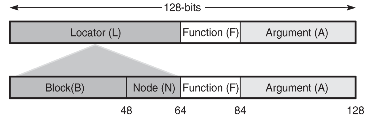
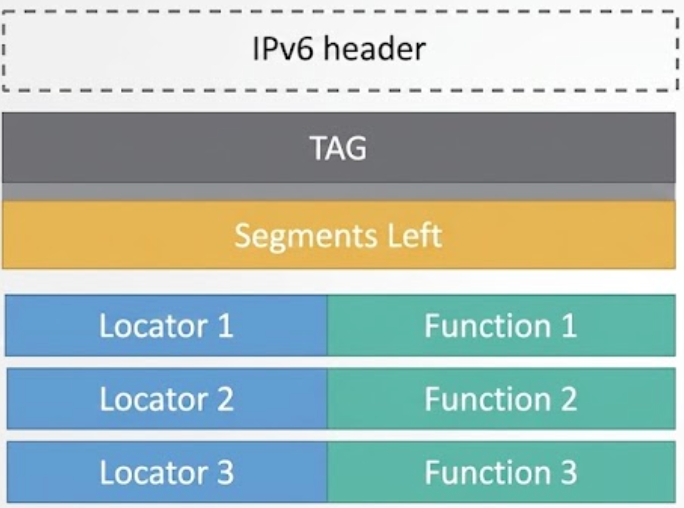
The essence of SRv6 "network programming": it treats the 128-bit IPv6 address not merely as an "address," but as an "instruction." The Locator specifies where to go (routing/addressing), while the Function specifies what to do (the business action — such as decapsulation or entering a VRF).
2.2 Unified Addressing & Network Instruction Sets: Locator:Function:Args
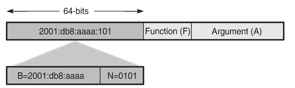
SRv6 abstracts network nodes and service behaviors into 128-bit IPv6 addresses (Segment IDs, or SIDs) split into three logical fields:
Locator: Guarantees network-wide Underlay reachability. Intermediate nodes perform Longest Prefix Matching (LPM) using standard IPv6 routing (e.g., BGP/OSPFv3) without maintaining complex tunnel tables.Function: Specifies the execution instruction at the destination node.End.DT4/End.DT6: Decapsulate and perform an IPv4/IPv6 table lookup in a designated VRF (Layer 3 multi-tenancy).End.DX2: Decapsulate and forward the inner Layer 2 frame to a designated interface (Layer 2 EVPN service).Args(Arguments): Carries flow-matching, security metadata, or network telemetry data.
 2.3 L3VPN & EVPN over SRv6 (BE Mode): Zero-SRH Flat Multi-Tenant Transport
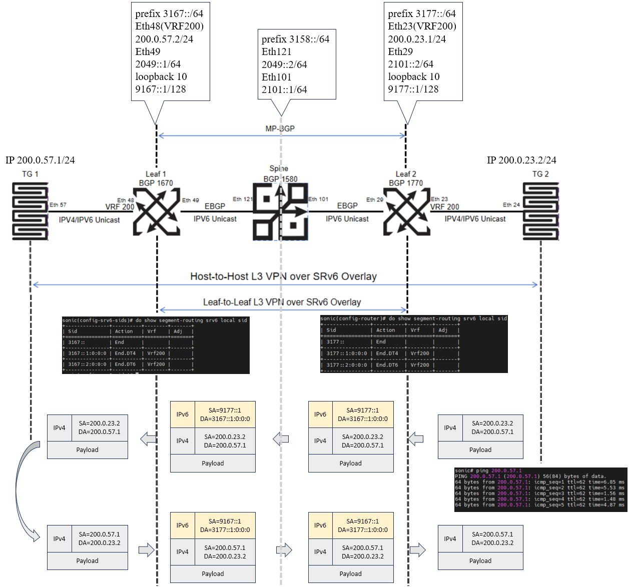
The control plane still relies on the mature BGP-EVPN or BGP L3VPN, but the implementation is significantly simplified: During route advertisement, the egress leaf (Leaf 1) directly advertises the service SID to the entire network via the BGP Prefix-SID attribute (e.g., 3167::1:0:0:0).
Step 1 (Ingress Leaf entry): Leaf 2, acting as the ingress node, receives data from tenant TG2, performs a table lookup matching the target SID, and — for pure Layer 3 services such as L3VPN or EVPN Type-5 — strips the original packet's Layer 2 MAC header and encapsulates the inner IP packet directly inside an outer SRv6 IPv6 header (DA =
3167::1:0:0:0). At the same time, the outer source address (SA) must be strictly set to the local node's fixed loopback address (e.g., SA =9177::1) to ensure PMTU discovery and OAM troubleshooting mechanisms function correctly.Step 2 (Spine pure/"naked" transit): The intermediate spine node receives the packet, examines only the first 64 bits of the DA (the Locator), and forwards it via ordinary longest-prefix-match (LPM) hardware lookup — without decapsulating the packet or inspecting the latter half (the Function) at all.
Step 3 (Egress Leaf exit): The packet arrives at Leaf 1. Leaf 1 recognizes that the DA is its own Locator, reads the Function field (End.DT4), strips the IPv6 outer shell, and delivers the original packet into the specified tenant VRF, reaching the destination TG1.
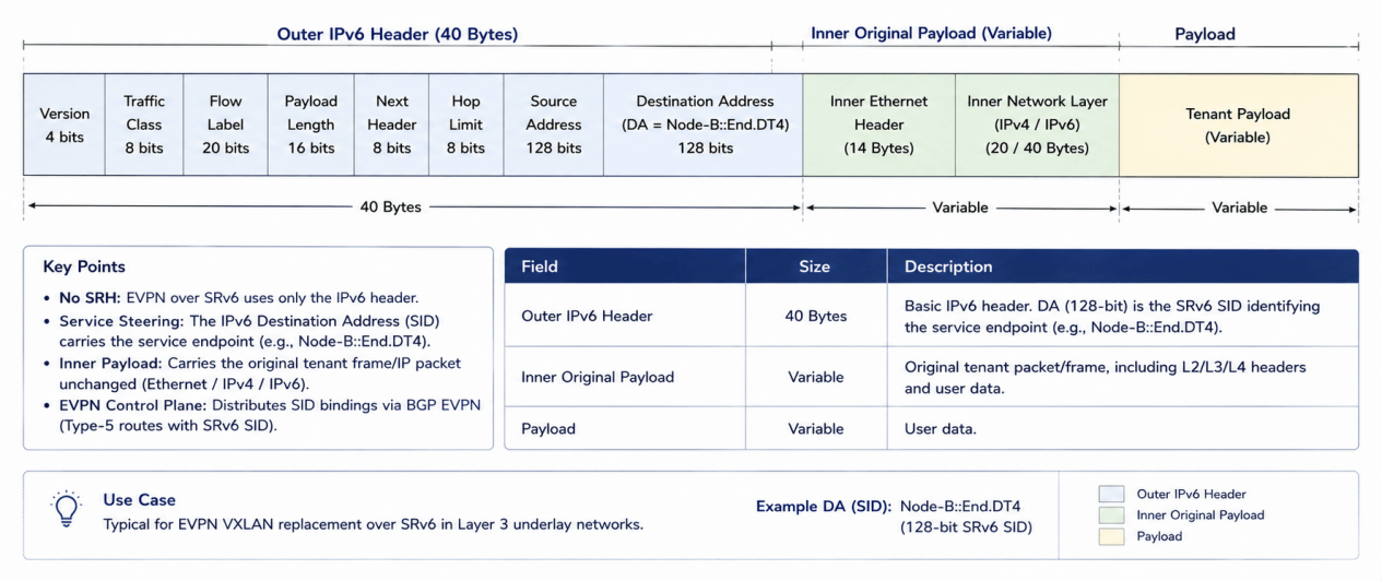 2.4 SRv6 BE vs. SRv6 TE
SRv6 BE (Best Effort — the vast majority of intra-data-center scenarios)*
Characteristics: No SRH extension header required — only the standard 40-byte outer IPv6 header is used.
Principle: The outer IPv6 DA itself serves as the SID. Nodes along the path forward via the default IGP/ECMP shortest path. Overhead is extremely low, making it a drop-in replacement for traditional plain VxLAN.
SRv6 TE (Traffic Engineering — AI large-model / compute-scheduling scenarios)
Characteristics: To address RoCEv2 elephant-flow congestion, an SRH extension header must be inserted, carrying a SID list of multiple waypoints.
Principle: Used to explicitly specify a path — for example, to route around a congested link, or to force traffic through a firewall via service function chaining (SFC).
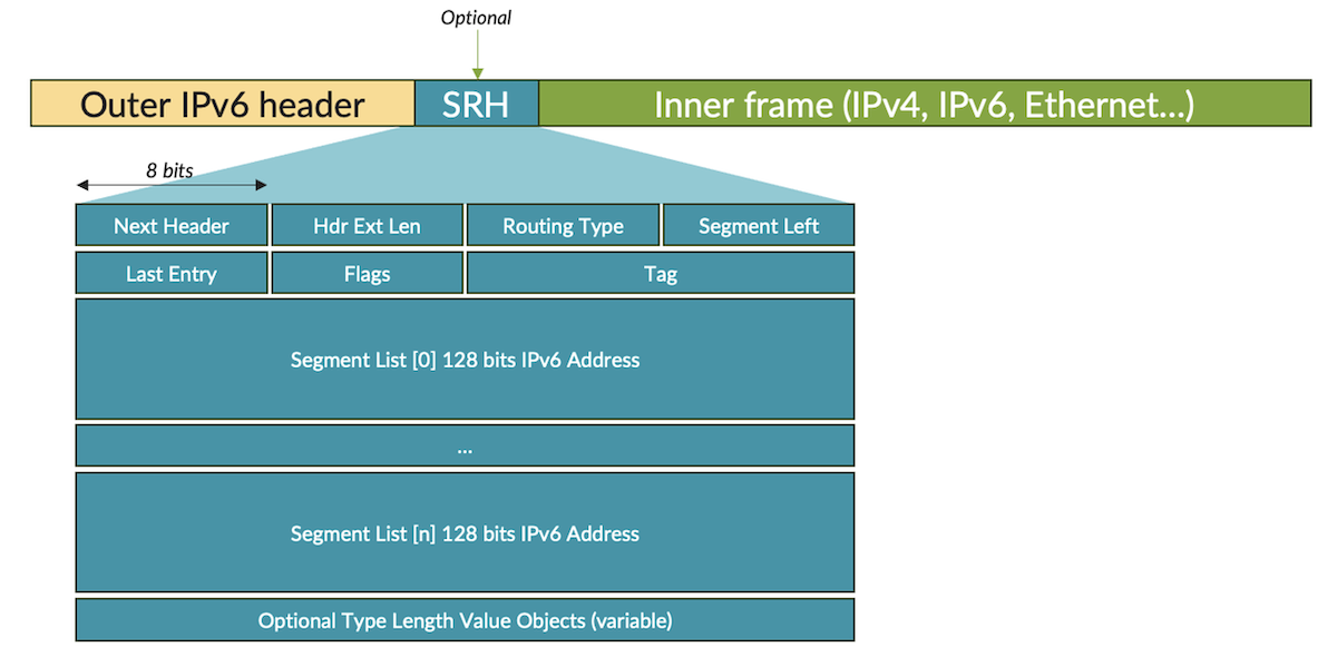
2.5 SRv6 Policy & Intelligent Source Routing
To address RoCEv2 elephant flow congestion in AI clusters, SRv6 provides deterministic traffic orchestration:
Explicit Path Selection: The Ingress Leaf or a centralized controller pushes a Segment List into packet headers based on real-time telemetry, routing around congested links.
Stateless Intermediate Forwarding: Intermediate Spine switches forward traffic based on the active SID and decrement the pointer (
Segments Leftminus 1), eliminating granular flow table provisioning on core switches.
2.6 SID Compression: Resolving MTU Overhead
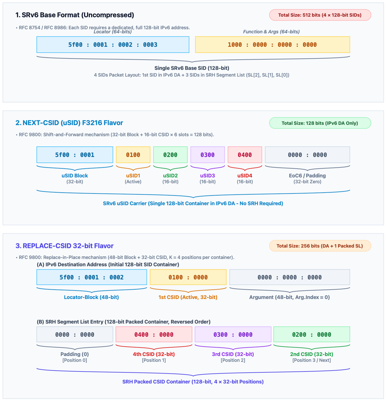
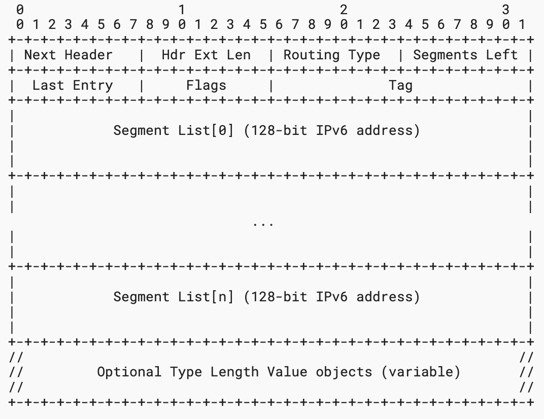 To address packet expansion caused by standard 128-bit Segment Routing Headers (SRH), RFC 9800 defines two compression mechanisms: NEXT-C-SID and REPLACE-C-SID. By packing multiple short opcodes (16-bit or 32-bit) into a single 128-bit IPv6 destination container, packet overhead is minimized while maintaining standard throughput for small packets and ASIC lookup efficiency.
NEXT-C-SID (shift-and-forward): Uses a "shift-and-forward" mechanism. Multiple 16-bit short instructions are arranged sequentially in the IPv6 destination address, like cartridges in a magazine. At each hop, the hardware shifts the address contents left as a block, exposing the next node's instruction — this approach can even eliminate the need for an SRH extension header entirely.
REPLACE-C-SID (replace-in-place): Uses a "replace-in-place" mechanism. It still uses an SRH extension header, but compresses it to the extreme (e.g., packing four 32-bit short instructions into a single 128-bit container). At each hop, the router reads the next short instruction out of the extension-header container and directly overwrites the dynamic field of the outer destination IP address in place, guiding forwarding to the next hop.
 2.7 How the Control Plane Works
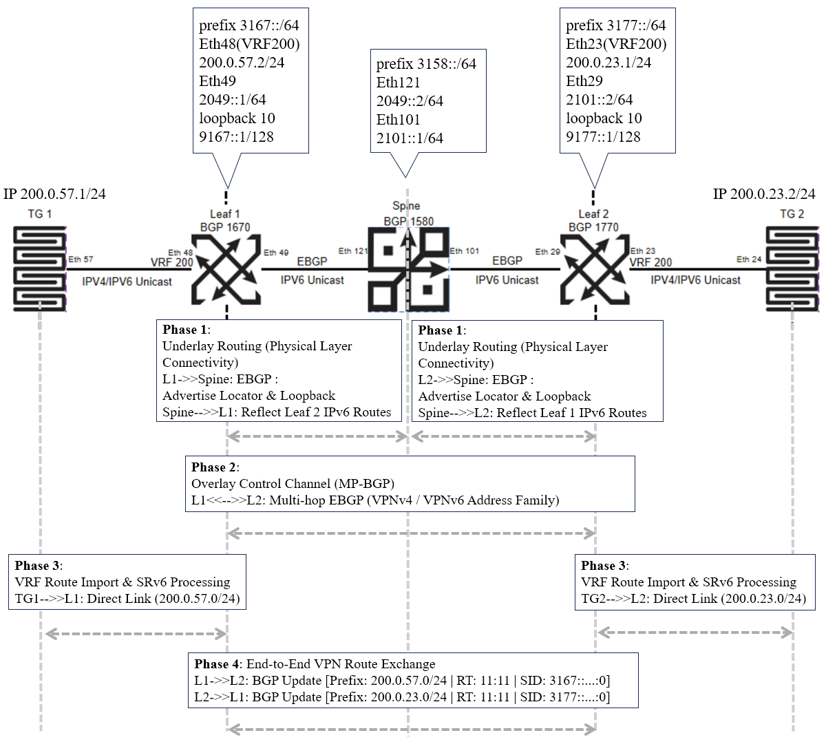
Finally, let's look at the working principles of the control plane. Across the network, nodes advertise their Locator prefixes and loopback addresses to one another via global IS-IS or eBGP, establishing underlay physical connectivity (Phase 1). A multi-hop MP-BGP end-to-end control channel is then established directly between the loopback addresses of the two edge leaves (e.g., 9167::1 and 9177::1), spanning the intermediate spine node (Phase 2).
During service onboarding, the leaf node imports its locally connected tenant private routes into a VRF, automatically assigns the corresponding SRv6 service instruction (e.g., End.DT4), and tags it with a Route Target (RT) — completing the route's "packaging for shipment" (Phase 3). Finally, the leaf node generates a BGP Update message containing the "private prefix + RT + SID" and sends it to the remote end; upon receipt, the peer imports the route into its local VRF based on the RT, automatically building the mapping table between the inner private IP and the outer SRv6 SID (Phase 4). It's worth noting that the example shown here illustrates the SRv6 L3VPN process based on the BGP VPNv4/v6 address family; the underlying logic is identical to BGP-EVPN based on MAC/IP route propagation — both efficiently distribute SID mappings via the control plane to drive rapid encapsulation and forwarding on the data plane.
3. Typical SRv6 Deployment Scenarios in Data Centers
3.1 SRv6 in AI Backend Networks — MRC Architecture
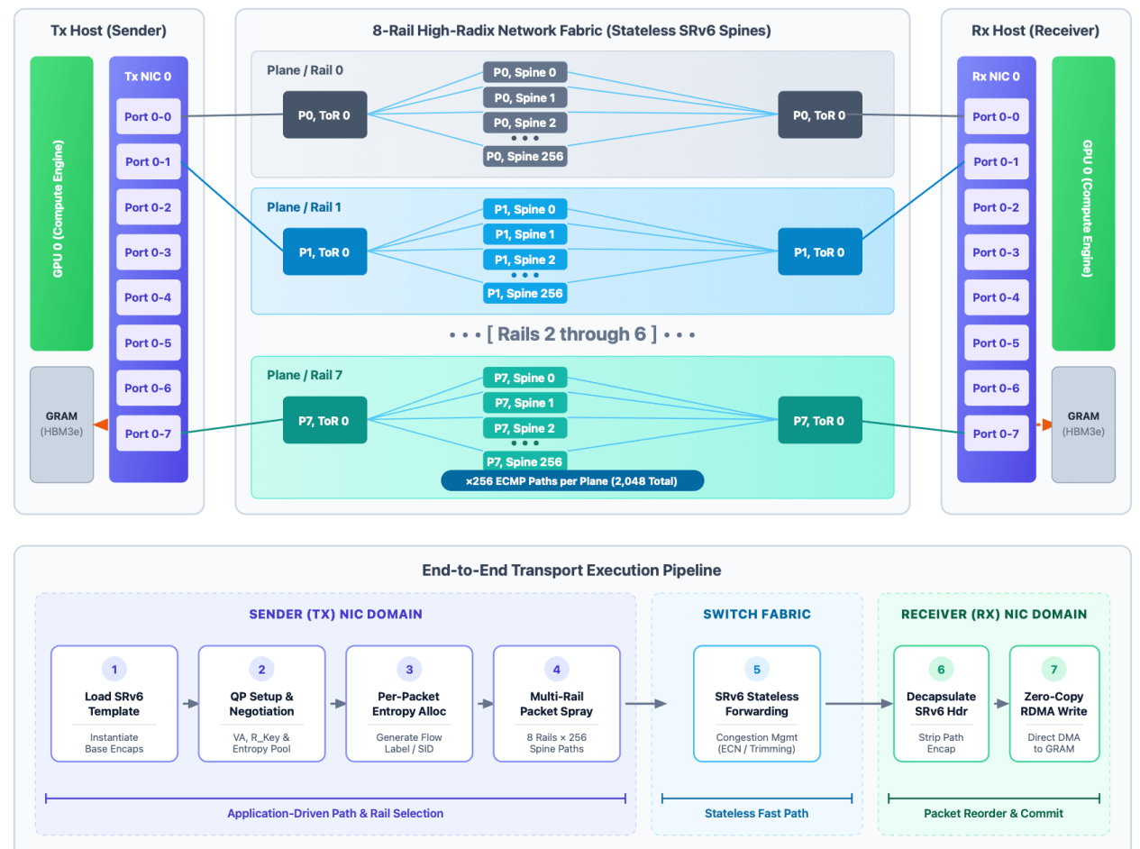
The Multi-Rail Carrier (MRC) architecture—developed collaboratively by OpenAI, Microsoft, NVIDIA, AMD, Intel, and Broadcom—demonstrates SRv6 in AI backends. A key principle of SRv6 is giving applications direct control over their network path. Implementing MRC at the transport layer creates a programmable fabric where the transport stack selects paths on a per-packet basis. Sprinkling packets across stateless paths and planes avoids low-entropy flow collisions common in traditional ECMP setups.
 3.2 SRv6 Container Networking — NetPila
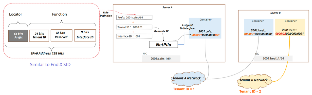
Alibaba Cloud's NetPila illustrates how SRv6 improves container networking beyond VXLAN tunnels. Embedding tenant and interface identifiers directly into the IPv6/SRv6 address model enables tunnel-less Pod-to-Pod connectivity and tight endpoint-network integration.
 3.3 SRv6 DCI & Backbone Networking — eCore
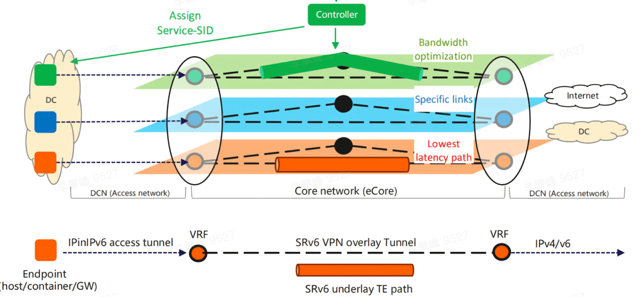
Alibaba Cloud's eCore is an IPv6/SRv6 backbone and DCI architecture. Utilizing a unified IPv6 Underlay and SRv6 Traffic Engineering, eCore shifts path selection from hop-by-hop decisions to programmable, end-to-end control. In AI deployments, server-side applications set Flow Labels based on workload properties and QoS requirements, which the network maps to specific SRv6 SID-Lists for optimized path selection (e.g., RDMA, high-bandwidth, or low-latency links).
 3.4 SRv6 Data Center Frontend Networks
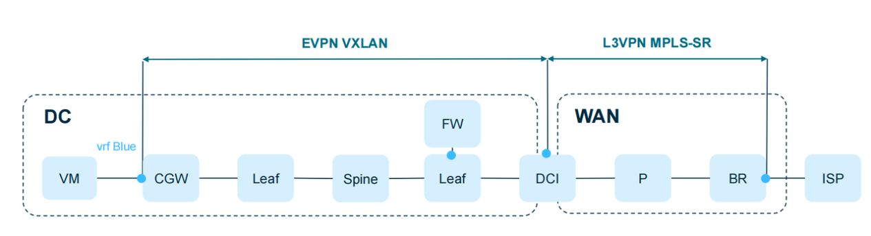
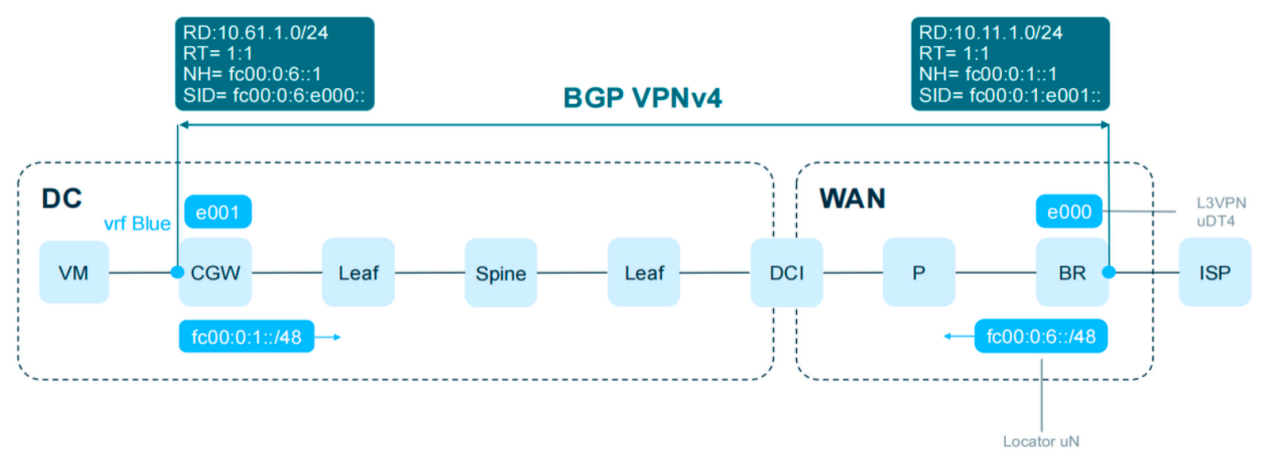
Eliminating DCI Bottlenecks: Removes EVPN-to-MPLS translation logic on DCI gateways. DCI devices function as high-capacity IPv6 routers, avoiding multi-vendor interoperability issues.
Simplified NFV Service Chaining: NFV instances (e.g., Cloud Gateways, Firewalls) running on x86 hosts natively process IPv6/SRv6 in kernel, replacing hardcoded routes with flexible instruction sequences.
Unified Control: Replaces multi-segment "DC + DCI + WAN" designs with an end-to-end, flat L3VPN architecture.
 3.5 SRv6 Service Chaining
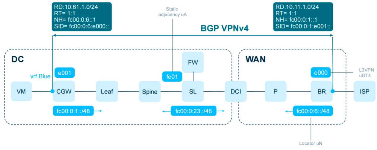
Services as SIDs: In VXLAN networks, service nodes (such as firewalls) act as topological "black holes" requiring static policy routing. In SRv6, every service node or interface receives a globally unique SID. Service chains append a Segment List of service SIDs to the packet header, allowing automatic network orchestration.
Unified Control and Forwarding: VXLAN Overlay networks require separate control planes (e.g., EVPN) and controller-driven service policies. SRv6 unifies control (IGP/BGP SID advertisements) and data planes (SID encapsulation), simplifying the stack.
Stateless Service Chaining: Traditional service chains require state maintenance across service nodes. SRv6 service chaining is completely stateless—pathing and service ordering are driven entirely by the packet's SID list.
4. AsterNOS SRv6 Specifications and Roadmap
To support end-to-end SRv6 Fabric deployments, AsterNOS provides a comprehensive feature roadmap. AsterNOS supports standard SRv6 and REPLACE-C-SID (G-SID) compression, with full NEXT-C-SID (uSID) support arriving in Q4 to assist enterprise AI networks.
Category | Sub-Item | Feature Description | Schedule / Status |
SRv6 Endpoint Behaviors | End | Endpoint | Supported |
End.X | Endpoint with L3 cross-connect (L3VPN) | Supported | |
End.DT4 | Endpoint with decapsulation and IPv4 table lookup (L3VPN) | Supported | |
End.DT6 | Endpoint with decapsulation and IPv6 table lookup (L3VPN) | Supported | |
End.DT46 | Endpoint with decapsulation and IP table lookup (L3VPN) | Supported | |
End.DX4 | Endpoint with decapsulation and IPv4 cross-connect (L3VPN) | Q4 | |
End.DX6 | Endpoint with decapsulation and IPv6 cross-connect (L3VPN) | Q4 | |
End.DX2 | Endpoint with decapsulation and L2 cross-connect (L2VPN) | Supported | |
End.DT2M | Endpoint with decapsulation and L2 broadcast (L2VPN) | Supported | |
End.DT2U | Endpoint with decapsulation and L2 unicast FDB lookup (L2VPN) | Supported | |
SID Compression | uSID | uSID (NEXT-CSID) compression | Q4 |
G-SID | G-SID (REPLACE-CSID) compression, 12 slots | Supported | |
Encapsulation Modes | H.Insert.Red | Insert SRH in IPv6 with reduced encapsulation | Q4 |
H.Encaps.Red | Encapsulate SR headend with reduced encapsulation | Supported | |
H.Encaps.L2.Red | Encapsulate SR headend over L2 layer with reduced encapsulation | Q4 | |
Node Flavors | USD | Ultimate Segment Decapsulation | Supported |
COC | G-SID mode, update DIP using compressed G-SID | Supported | |
IGP Routing | ISIS | IS-IS extensions for SRv6 | Supported |
ISIS FRR | TI-LFA high availability | Supported | |
OSPF | OSPFv3 extensions for SRv6 | Q4 | |
OSPF FRR | TI-LFA high availability | Q4 | |
BGP | BGP | BGP extensions for SRv6 | Supported |
SRv6-BE | L3VPN | L3VPN over SRv6-BE | Supported |
EVPN L2VPN | VPLS (Type 1, 2, 3, 4) | Q3 | |
VPWS (Type 1, 4) | Q3 | ||
CCC | Q3 | ||
Multi-homing | Q4 | ||
EVPN L3VPN | Type 5 (IP Prefix Route) | Supported | |
SRv6-TE | Static TE Policy | Static SRv6 TE Policy | Supported |
TE Policy | Dynamic SRv6 TE Policy | Q4 | |
L3VPN | L3VPN over SRv6-TE | Supported | |
EVPN L2VPN | VPLS / VPWS / CCC / Multi-homing over SRv6-TE | Q3 / Q4 | |
EVPN L3VPN | EVPN L3VPN (Type 1–5) over SRv6-TE | Supported | |
Telemetry | Telemetry | Streaming Telemetry data collection | Supported |
BGP-EPE | BGP-EPE | Egress Peer Engineering SID allocation | Supported |
BGP-LS | SRv6 SID NLRI | SRv6 SID Info / Endpoint Behavior / BGP Peer Node SID TLV | Q4 |
Node NLRI | SRv6 Capabilities / Node MSD Types TLV | Q4 | |
Link NLRI | SRv6 End.X / LAN End.X / Link MSD Types TLV | Q4 | |
Prefix NLRI | SRv6 SID Structure / Locator TLV | Q4 | |
PCEP | PCEP | Path Computation Element Protocol for SRv6 | Q4 |
SBFD | SBFD | Seamless BFD for SRv6 Policy | Q4 |
SRv6 OAM | SRv6 OAM | Destination SID and PW reachability verification | Q4 |
Flex-Algo | Flex-Algo | Flexible Algorithm for custom IGP path computation | Q4 |
OAM Tools | SID Ping | SID reachability ping | Q4 |
SID Tracert | SID path trace | Q4 | |
TE Policy Ping | TE Policy reachability ping | Q4 | |
TE Policy Tracert | TE Policy path trace | Q4 | |
TWAMP | TWAMP | Two-Way Active Measurement Protocol | Supported |