
1 When one GPU is no longer sufficient
As model size, context length, concurrency, and AI workloads grow, the memory and compute of a single GPU reach their limit. Inference systems then require:
Multiple GPUs
Multiple GPU servers
Distributed inference
Prefill/decode disaggregation
Distributed KV Cache
The problem moves from GPU optimization to GPU cluster networking. Communication between GPUs becomes a component of system performance.
2 From GPU memory to GPU-to-GPU communication
Consider an AI cluster with multiple GPU servers:
        Server A                         Server B
+--------------------+           +--------------------+
| GPU 0   GPU 1      |           | GPU 4   GPU 5      |
|                    |           |                    |
| KV Cache           |           | KV Cache           |
+---------+----------+           +----------+---------+
          |                                 |
          +---------- AI Network -----------+
                         |
                    RoCE Switch
When the data stays inside one server, GPUs communicate over high-speed interconnects such as NVLink and NVSwitch. When computation and KV Cache span servers, the data must cross the network. The network then connects GPUs and not only servers. It forms a high-speed data path between GPU memories.
3 RoCE: Ethernet as a GPU fabric
RoCE (RDMA over Converged Ethernet) runs RDMA over standard Ethernet. With GPUs and NICs that support GPUDirect RDMA, data transfers directly between GPUs:
GPU Memory
    | PCIe
RDMA NIC
    | RoCEv2
AI Switch
    | RoCEv2
RDMA NIC
    | PCIe
GPU Memory
Compared with CPU-based data movement, this path reduces data copies and CPU involvement. In a large AI cluster, RoCE moves data between distributed GPU resources with high bandwidth and low latency. KV Cache is one type of data that uses this path.
4 KV Cache and the network
Not every LLM inference architecture reads KV Cache from a remote GPU for each generated token. High-performance inference systems limit remote access, because remote GPU memory is slower than local GPU memory. Systems keep KV locality, which places computation close to the KV Cache.
KV Cache or related intermediate data must move between GPUs and servers when the system uses:
Distributed inference
Prefill/decode disaggregation
Distributed KV Cache
KV-aware routing
Multi-node serving
Example:
          User Request
                |
        +---------------+
        | Prefill GPUs  |
        +-------+-------+
                |
            KV Cache
                |
          RoCE Network
                |
        +-------+-------+
        | Decode GPUs   |
        +---------------+
The prefill cluster processes long prompts and then transfers the KV Cache to the decode cluster. The decode cluster uses the KV Cache to generate new tokens. In this architecture, the network is part of the inference data path, and network performance affects application performance.
5 Requirements of an AI RoCE network
Basic connectivity is not sufficient once the network is the data path of a GPU cluster. An AI RoCE network must address five core areas.
5.1 Bandwidth
AI workloads drive network speeds from 100G to 200G, 400G, 800G, and 1.6T. When hundreds or thousands of GPUs exchange data at the same time, insufficient bandwidth leaves GPUs waiting for data and reduces compute utilization. High-speed GPUs require a high-speed network fabric.
5.2 Latency
In distributed AI workloads, network latency means the GPU waits. A GPU that has finished its computation and is waiting for the next batch of data is underused. The network requires:
Low latency
Low jitter
Predictable latency
Low tail latency
In large GPU clusters, tail latency (P99, P999) is a more relevant measure than average latency.
6 Switch latency of 500 ns
Switch forwarding latency is part of the data path:
GPU → NIC → Switch → NIC → GPUEach network hop adds latency. As cluster size and communication frequency increase, switch latency has more effect on total latency. The Asteraix CX-N AI switch series provides forwarding latency of 500 ns on 12.8T models and 560 ns on 51.2T models, for building low-latency Ethernet fabrics for high-speed GPU clusters.
In 400G/800G AI networks, switch latency is one component of GPU-to-GPU end-to-end communication latency. Reducing latency per hop reduces the total waiting time for data exchange.
7 RoCE requires more than bandwidth
Support for RoCEv2 does not mean a switch is optimized for AI workloads. The requirement for an AI RoCE network is to keep thousands of high-speed GPU flows moving without congestion. This requires the following technologies:
PFC (Priority Flow Control): reduces packet loss for traffic of specific priorities.
ECN (Explicit Congestion Notification): network devices mark congestion explicitly, so that end devices detect it.
Congestion control: controls congestion under high-concurrency GPU traffic and prevents severe congestion.
QoS: assigns priorities to different types of AI traffic so that critical traffic receives stable network resources.
Intelligent buffer management.
AI clusters generate burst traffic and incast traffic. In incast, multiple GPUs send large amounts of data to the same destination at nearly the same time, and the traffic concentrates in a short period. This causes congestion.
GPU 1 --+
GPU 2 --+
GPU 3 --+
GPU 4 --+
GPU 5 --+--> GPU 20
GPU 6 --+
GPU 7 --+
GPU 8 --+
A large buffer absorbs burst traffic temporarily and reduces packet loss and delay caused by instantaneous congestion. An AI network therefore requires high bandwidth, a large buffer, and intelligent congestion management. The Asteraix CX864E-N provides 51.2T switching capacity and a 200 MB buffer for burst and incast traffic in AI scenarios.
Bandwidth determines the data rate. Buffer capacity determines how much burst traffic the network can absorb.
8 Adaptive load balancing
As AI clusters grow from hundreds to thousands of GPUs, network traffic becomes more dynamic and harder to predict. Traditional ECMP distributes traffic across multiple paths but does not respond to real-time congestion. In a typical leaf-spine AI fabric:
                  Spine 1
                 /       \
GPU ---------- Leaf ------- GPU
                 \       /
                  Spine 2
If a large share of AI traffic concentrates on one path, that path congests:
Spine 1
  ↓ link utilization rises
  ↓ packet queues accumulate
  ↓ latency increases
  ↓ GPU communication performance drops
Other paths may still have available bandwidth. Load balancing for AI workloads is therefore more than the use of multiple paths. The network must detect the state of each path in real time and adjust traffic distribution to match.
From static ECMP to adaptive load balancing
AsterNOS provides INT-Driven Adaptive Routing (IAR). IAR uses In-Band Network Telemetry (INT) to obtain real-time link utilization and assigns traffic to available paths according to network state.
AsterNOS supports the following forwarding mechanisms, depending on workload and network design:
Flow-based ECMP: distributes different flows across multiple paths.
Flowlet-based load balancing: divides a flow into flowlets according to the idle time between packets and forwards different flowlets over different paths. This improves load balancing and keeps packets in order at the destination.
Packet spray: distributes the individual packets of one flow across different paths. This gives near-ideal load balancing and aligns with the direction of UEC. Packets can arrive out of order, so the destination must reorder them.
WCMP: assigns different weights to different paths, so that more traffic goes to paths with higher capacity or lower congestion.
These mechanisms move the network from static path selection to traffic scheduling based on real-time network state, which uses the network resources of the AI fabric more fully.
Load balancing for large AI clusters
The objective is to maximize the network utilization of the whole AI fabric, in addition to avoiding congestion on a single link. With INT-driven adaptive routing and multiple forwarding mechanisms, AsterNOS can raise network utilization to 97%. It supports large-scale load balancing with up to 256-way path selection and 4K groups.
The objective for AI infrastructure changes from keeping the network connected to keeping the GPU cluster efficiently connected: the network provides balanced, low-congestion connectivity to the GPU cluster.
Optimizing AI traffic beyond load balancing
Load balancing is one part of AI network optimization. Many AI workloads also generate multicast communication. AsterNOS provides Multicast Acceleration, which lets the switch replicate RDMA messages in the network instead of the GPU. This reduces GPU compute and communication overhead and reduces unnecessary network traffic, which improves the communication efficiency of the AI cluster.
This is why 400G, 800G, RoCEv2, RDMA, low latency, ECN, PFC, congestion control, ECMP, and adaptive routing are discussed more often. Each addresses the same problem.
9 How to keep GPUs busy
In a traditional data center, the network moves data from one server to another. In a large AI infrastructure, the role is different. An AI training job can run on hundreds, thousands, or more GPUs. These GPUs exchange data continuously, synchronize results, and perform collective communication. When the network is congested, latency increases, or data transfers slow down, GPUs wait. For GPU infrastructure, waiting means purchased compute capacity is not used. This dependence of large-scale distributed AI training on the network is the reason bandwidth, latency, and congestion control receive more attention.
The value of an AI network is therefore more than faster data transfer. The network must let GPUs, memory, and the network operate together: data arrives on time, congestion is controlled, bandwidth on different paths is used, and GPU waiting time is reduced.
Many AI networking technologies point to the same objective:
More network efficiency → Less GPU waiting → Higher infrastructure utilizationEach technology addresses one part:
400G and 800G meet higher bandwidth requirements.
RDMA and RoCEv2 provide efficient data exchange between GPU servers.
ECN, PFC, and congestion control handle congestion under high load.
ECMP and adaptive routing use multiple network paths.
The question in AI networking is how to build a network that keeps GPUs working instead of waiting. As AI infrastructure moves from single-machine optimization to cluster-level co-optimization, network optimization becomes a larger part of the work.
10 From single-GPU optimization to cluster-level optimization
In the early stage of AI development, optimization focused on the model and a single GPU. FP8, INT8, MXFP4, PagedAttention, continuous batching, and prefix caching reduce compute and memory overhead and raise single-GPU utilization and inference efficiency.
As workloads grow, systems move from a single GPU to multiple GPUs, then to multiple servers, and then to large GPU clusters. At this stage, optimizing the model or the GPU alone is not sufficient. The following factors affect workload performance directly:
Whether the GPU receives data continuously
Whether servers exchange data efficiently
Whether GPU memory and the network work together
AI infrastructure optimization moves from single-point optimization to system-level coordination. In addition to model optimization and GPU optimization, memory optimization and network optimization apply. An efficient AI infrastructure runs the model, GPU, memory, and network as one system. This is AI Infrastructure Co-Optimization.
11 CX-N: a high-performance Ethernet fabric for AI
AI performance is not determined by GPUs alone. As GPU clusters scale, the network fabric becomes a critical part of the overall system, especially for workloads that rely heavily on GPU-to-GPU communication.
The CX-N Series is designed as a high-performance Ethernet switching platform for AI training, AI inference, and high-performance data center networks, combining high bandwidth, ultra-low latency, and intelligent traffic management in an open SONiC-based architecture.
With 400G and 800G interfaces and switching capacities from 12.8T to 51.2T, CX-N provides the bandwidth required to build large-scale, high-performance AI fabrics.
CX-N is optimized for RoCEv2 / RDMA-based workloads, with network capabilities designed to keep high-volume GPU traffic moving efficiently across the fabric.
Key capabilities:
12.8T / 25.6T / 51.2T switching capacity
32×400G / 64×400G / 64×800G high-speed connectivity
Ultra-low switching latency of approximately 500 ns / 560 ns
RoCEv2 / RDMA support
PFC and ECN for congestion management
Advanced QoS for traffic prioritization
ECMP and Adaptive Routing for multi-path traffic distribution
Flowlet-based traffic optimization
High-performance telemetry and network visibility
SONiC-based open networking architecture
The ultra-low-latency architecture is relevant to AI workloads. With approximately 500 ns to 560 ns of switching latency, CX-N minimizes the network overhead between GPUs and helps create a more responsive communication fabric for distributed AI workloads.
Combined with RoCEv2, PFC/ECN, adaptive routing, and intelligent load balancing, CX-N is designed to provide bandwidth and also to build an Ethernet fabric that moves large amounts of GPU traffic with low latency and high network utilization.
In short: more bandwidth, less latency, smarter traffic management. That is the foundation of a high-performance Ethernet fabric for AI.
12 The AI network as part of the compute system
From the perspective of LLM inference, the technology chain is:
LLM Inference
      ↓
Token Generation
      ↓
KV Cache
      ↓
+-----------------------+----------------------+
| Local GPU Memory      | Distributed GPU      |
+-----------------------+----------+-----------+
                                   ↓
                             RoCE / RDMA
                                   ↓
                          AI Ethernet Fabric
                                   ↓
      +------------------+---------------+------------------+
      | 400/800G         | Low latency   | Congestion       |
      | Bandwidth        | 500/560 ns    | control          |
      +------------------+---------------+------------------+
                                   ↓
                        Higher GPU utilization
                                   ↓
                  Higher AI inference efficiency
Optimizing AI inference is no longer only about optimizing the GPU. When GPU resources are distributed across multiple servers, the network becomes part of the compute system.
Conclusion
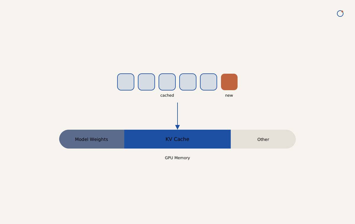
The KV Cache removes a large amount of repeated computation in LLM inference. As context length, concurrency, and model scale grow, it also increases GPU memory use and data-movement load. When AI workloads move from a single GPU and a single server to multi-GPU and cross-server deployment, the KV Cache and other intermediate data must move efficiently between distributed GPU resources.
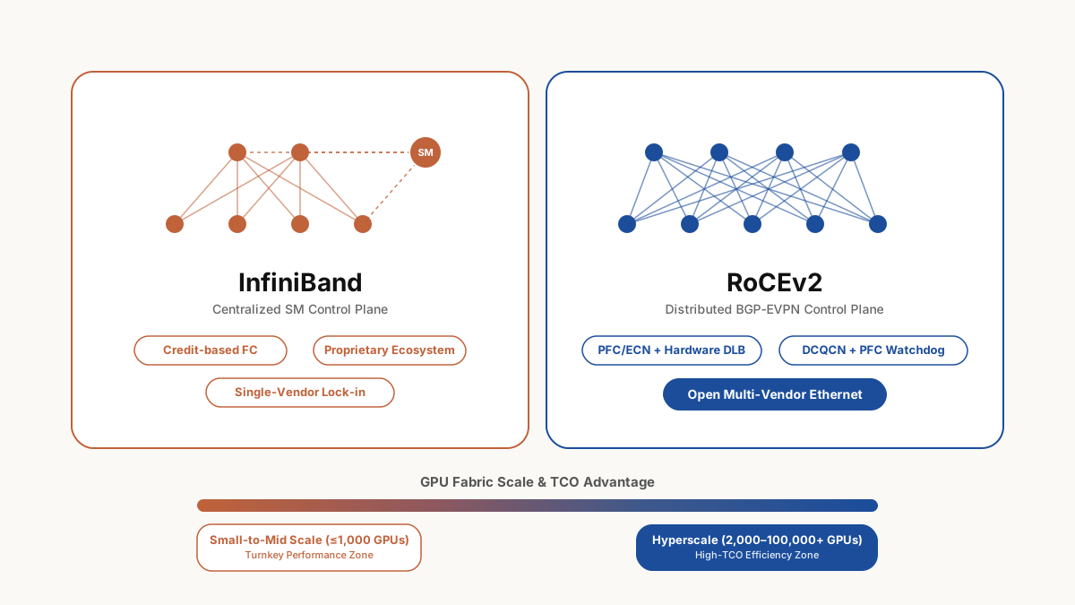
RoCEv2 is then more than a network protocol. It is the communication fabric that connects distributed GPU resources.
An AI network cannot be evaluated by a "RoCE supported" label alone. It requires:
High bandwidth + ultra-low latency + low loss + congestion control + intelligent load balancing + high visibility
The objective is to keep GPUs busy and AI workloads moving.
Asteraix CX-N combines 400G/800G high-speed Ethernet, ultra-low-latency switching, RoCEv2/RDMA support, and AI-oriented traffic optimization to build an open, high-performance network fabric for distributed AI infrastructure.
When GPUs are the engine of AI, the network is the road that determines how fast that engine can run.