800G AI Switch Best Practices for Medium-to-Large-Scale AI Computing Backend Networks
Preface
This document provides a detailed guide for using Asteraix’s CX864E-N data center switch to build a standardized network solution for medium-to-large-scale AI computing backend networks. It adopts a 2-tier Clos topology based on a Rail-optimized architecture, including configuration guidance and operational maintenance procedures.
Target Audience
This manual is intended for solution planning, design, and on-site deployment personnel. Readers should have the following background knowledge:
- Familiarity with Asterfusion data center network switch products
- Understanding of RoCE, PFC, and ECN technologies
Revision History
| Date | Version | Change Description |
| 2026-02-02 | V1.0 | Initial release |
1 Overview
Medium-to-large-scale AI cluster backend networks can be deployed using a Rail-optimized (track-optimized) architecture.
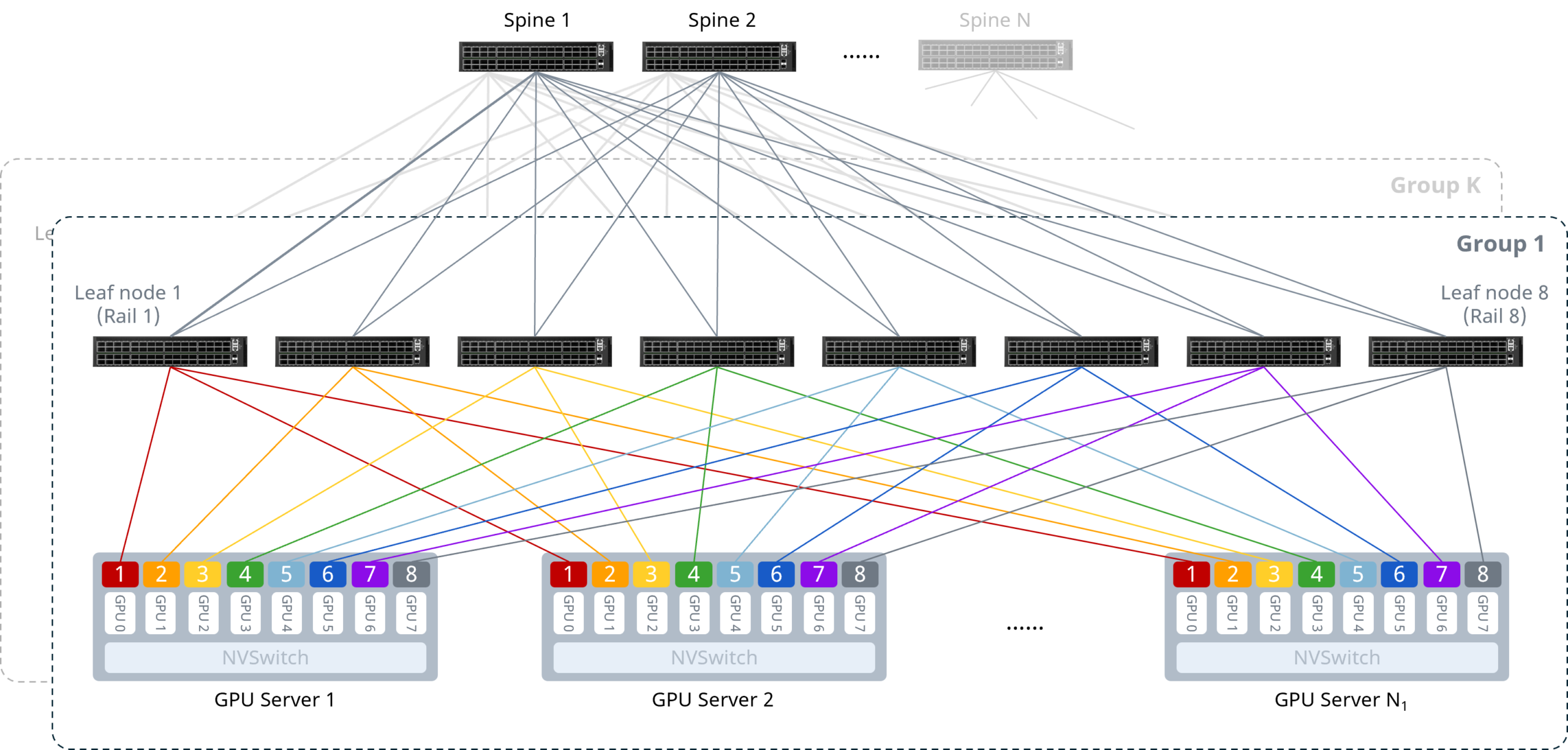
As shown above, the core design principle is to connect the NICs of the same index on each server to the same Leaf switch, ensuring that multi-machine GPU communication occurs with the fewest possible hops. Under this design, communication between GPU nodes can leverage NVSwitch[1] internal paths, requiring only a single hop and avoiding multiple switches and additional latency. The specifics are as follows:
- Intra-server interconnect: 8 GPUs connect to the NVSwitch via NVLink bus, enabling low-latency intra-server GPU communication and reducing Scale-Out network transfer pressure.
- Server-to-network interconnect: All servers follow a unified cabling convention — NICs connect to Leaf switches in the pattern NIC1→Leaf1, NIC2→Leaf2, etc., each connecting to a different Leaf switch.
Network-level interconnect: Leaf and Spine switches use full-mesh interconnect in a 2-tier Clos topology.
[1] NVSwitch is a high-speed NVLink switch chip developed by NVIDIA, enabling multiple GPUs to communicate at the maximum NVLink speed in a Scale-Up network.
2 Typical Configuration Example
The following example illustrates building an AI cluster of 64 compute nodes (4 GPUs per server, 256 GPUs total) using 6 CX864E-N switches — 2 as Spine nodes and 4 as Leaf nodes. The key configuration concepts are:
- Each GPU has a dedicated NIC. Each server’s NICs connect to Leaf switches following the pattern NIC1→Leaf1, NIC2→Leaf2, …, so that each Rail has its own subnet, with the Leaf switch acting as the default gateway for the Rail.
- The network uses a 2-tier Clos topology. Spine and Leaf switches use full-mesh interconnect with IPv6 link-local addresses to establish unnumbered BGP peering, advertise Rail subnet routes, and perform route exchange — eliminating the need to assign IP addresses to Leaf-Spine interconnect interfaces.
- The downstream-to-upstream capacity ratio at Leaf must strictly follow a 1:1 convergence ratio to ensure lossless transmission.
- Leaf and Spine switches enable one-click RoCE and load-balancing features to build a lossless network.
2.1 Network Topology
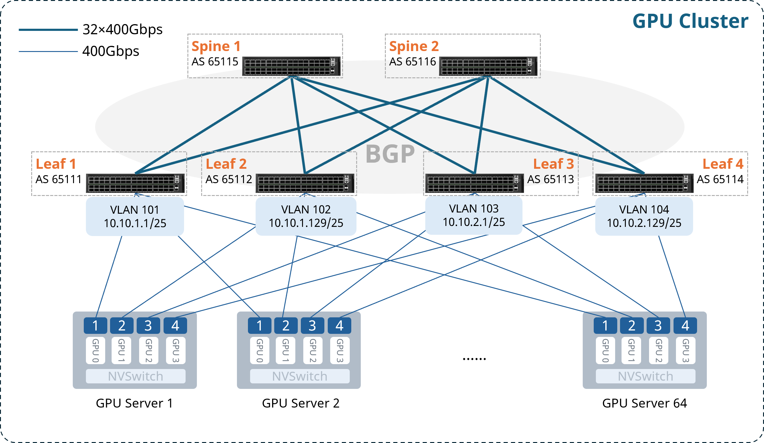
Note: For ease of subsequent configuration and deployment, it is recommended that the upper-half ports of each Leaf switch connect to servers, and the lower-half ports connect to Spines.
AS numbers, Loopback addresses, and gateway VLAN IP addresses for each node are allocated as follows:
Table 2-1 AS Number and Loopback IP Address Allocation
| Device | AS Number | Loopback 0 IP Address |
| Leaf1 | 65111 | 10.1.0.111/32 |
| Leaf2 | 65112 | 10.1.0.112/32 |
| Leaf3 | 65113 | 10.1.0.113/32 |
| Leaf4 | 65114 | 10.1.0.114/32 |
| Spine1 | 65115 | 10.1.0.115/32 |
| Spine2 | 65116 | 10.1.0.116/32 |
Table 2-2 Gateway VLAN IP Address Allocation
| Device | VLAN | Gateway IP Address |
| Leaf1 | 101 | 10.10.1.1/25 |
| Leaf2 | 102 | 10.10.1.129/25 |
| Leaf3 | 103 | 10.10.2.1/25 |
| Leaf4 | 104 | 10.10.2.129/25 |
2.2 Configuration Overview
Table 2-3 Configuration Overview
| Device Type | Configuration Steps |
| Configure Leaf Switch | (Optional) Configure NIC-side port breakout |
| Configure gateway VLAN and IP address | |
| Configure BGP for Layer 3 reachability | |
| Enable one-click RoCE | |
| Configure ARS | |
| Configure Spine Switch | Configure BGP for Layer 3 reachability |
| Enable one-click RoCE | |
| Configure ARS and Hash seed |
2.3 Configuring the Leaf Switch
2.3.1 (Optional) Configure NIC-side Port Breakout
For scenarios using CX864E-N switches with 400G NICs, the downlink 800G ports need to be broken out into two 400G ports.
Table 2-4 Configure NIC-side Port Breakout
| Step Description | Leaf1 |
| Enter global configuration mode | configure terminal |
| Break out upper-half 800G ports | interface range ethernet 0/0-0/248 breakout 2x400G[200G] ! |
| If bulk interface config is not supported in the current version, execute individually: | interface ethernet 0/0 breakout 2x400G[200G] ! …… |
After completing the configuration above, you can verify the interface status with the show interface summary command.
2.3.2 Configure Gateway VLAN and IP Address
Table 2-5 Configure VLAN and Interface IP Address
| Step Description | Leaf1 |
| Set device hostname | hostname Leaf1 |
| Enter global configuration mode | configure terminal |
| Create gateway VLAN and assign IP address | vlan 101 ! interface vlan 101 ip address 10.10.1.1/25 exit ! |
| Add Leaf downlink ports to the VLAN | interface range ethernet 0/0-0/252 switchport access vlan 101 ! |
| If bulk config is not supported, execute individually: | interface ethernet 0/0 switchport access vlan 101 ! …… |
After completing the configuration, use show vlan summary to verify the VLAN configuration.
2.3.3 Configure BGP for Layer 3 Reachability
Enable IPv6 link-local on Leaf-Spine interconnect interfaces to establish unnumbered BGP peering and propagate routes.
Table 2-6 Configure BGP Peering on Leaf
| Step Description | Leaf1 |
| Enable IPv6 link-local on Leaf uplink interfaces | interface range ethernet 0/256-0/504 ipv6 use-link-local ! |
| If bulk config is not supported, execute individually: | interface ethernet 0/256 ipv6 use-link-local ! …… |
| Configure Loopback 0 IP address as Router-ID | interface loopback 0 ip address 10.1.0.111/32 ! |
| Configure BGP AS number and Router-ID; enable BGP max-med, multipath, and graceful-restart | router bgp 65111 bgp router-id 10.1.0.111 no bgp ebgp-requires-policy bgp bestpath as-path multipath-relax bgp max-med on-startup 300 bgp graceful-restart restart-time 240 bgp graceful-restart |
| Create unnumbered BGP peer group | neighbor PEER_unnumber_BGP peer-group neighbor PEER_unnumber_BGP remote-as external neighbor range ethernet 0/256-0/504 interface peer-group PEER_unnumber_BGP |
| If bulk config is not supported, execute individually: | neighbor PEER_unnumber_BGP peer-group neighbor PEER_unnumber_BGP remote-as external neighbor ethernet 0/256 interface peer-group PEER_unnumber_BGP neighbor ethernet 0/264 interface peer-group PEER_unnumber_BGP …… |
| Advertise Loopback and VLAN network routes | address-family ipv4 unicast redistribute connected exit-address-family ! |
2.3.4 Enable One-Click RoCE
The CX-N series switch supports queues 0–7 (8 queues total). Queues 3 and 4 are lossless queues (up to 2 lossless queues are supported); all other queues are lossy queues.
The default template uses the system default DSCP mapping. Queues 3 and 4 enable PFC and ECN. Queues 6 and 7 are configured with strict priority scheduling.
When creating a template, the following three parameters can be specified:
- cable-length: Specifies the cable length in meters, which affects the PFC and ECN parameter calculations. Options: 5m / 40m / 100m / 300m. If no exact match, choose the nearest value (e.g., for 10m actual cable length, select 5m).
- incast-level: Specifies the traffic Incast model, affecting PFC parameter calculations. Options: low (e.g., 1:1) / medium (e.g., 3:1) / high (e.g., 10:1). In GPU backend networks, low is generally recommended.
- traffic-model: Specifies the traffic type — throughput-sensitive, latency-sensitive, or balanced — which affects ECN parameter calculations. Options: throughput / latency / balance. In GPU backend networks, balance or throughput mode is generally recommended.
If the lossless RoCE configuration provided does not fully fit your business scenario, refer to Section 3.1 RoCE Tuning/Optimization for configuration adjustments and parameter fine-tuning to achieve optimal performance.
Table 2-7 Enable Easy RoCE
| Step Description | Leaf1 |
| (Optional) Modify lossless queues. Requires saving config and reloading to take effect. | no priority-flow-control enable 3 no priority-flow-control enable 4 priority-flow-control enable queue-id write reload |
| Select the one-click RoCE template and apply it to all interfaces | qos roce lossless cable-length 5m incast-level low traffic-model throughput qos service-policy roce_lossless_5m_low_throughput |
After completing the configuration, use show qos roce to verify the RoCE configuration. Example output:
Leaf1# show qos roce
Notice: Displaying configurations of in-use RoCE profiles
==> RoCE Profile: roce_lossless_5m_low_throughput | RoCE Policy Map: roce_lossless_5m_low_throughput_400g <==
+--------------------+-----------------+-----------------------------------------------------+
|                    | Operational     | Description                                         |
+====================+=================+=====================================================+
| Mode               | Lossless        | QoS RoCE mode                                       |
+--------------------+-----------------+-----------------------------------------------------+
| Status             | Bind: 0/0-0/252 | QoS RoCE binding status                             |
+--------------------+-----------------+-----------------------------------------------------+
| Cable Length       | 5m              | Cable length in meters for QoS RoCE lossless config |
+--------------------+-----------------+-----------------------------------------------------+
| Congestion-Control | -               | -                                                   |
|  - Congestion Mode | ECN             | Congestion control mode                             |
|  - Enabled TC      | 3,4             | Congestion control config enabled traffic class     |
|  - Max Threshold   | 10094080        | Congestion control config max threshold             |
|  - Min Threshold   | 2000000         | Congestion control config max threshold             |
+--------------------+-----------------+-----------------------------------------------------+
| PFC                | -               | -                                                   |
|  - PFC Priority    | 3,4             | PFC enabled switch priority                         |
|  - TX Status       | Enabled         | PFC RX status                                       |
|  - RX Status       | Enabled         | PFC TX status                                       |
+--------------------+-----------------+-----------------------------------------------------+
| Trust              | -               | -                                                   |
|  - Trust Mode      | DSCP            | Trust setting for packet classification             |
+--------------------+-----------------+-----------------------------------------------------+
====> RoCE DSCP->SP Mapping Configurations <====
+-------------------------+-------------------+
| DSCP                    | Switch Priority   |
+=========================+===================+
| 0,1,2,3,4,5,6,7         | 0                 |
| 8,9,10,11,12,13,14,15   | 1                 |
| 16,17,18,19,20,21,22,23 | 2                 |
| 24,25,26,27,28,29,30,31 | 3                 |
| 32,33,34,35,36,37,38,39 | 4                 |
| 40,41,42,43,44,45,46,47 | 5                 |
| 48,49,50,51,52,53,54,55 | 6                 |
| 56,57,58,59,60,61,62,63 | 7                 |
+-------------------------+-------------------+
====> RoCE SP->TC Mapping & ETS Configurations <====
+-------------------+--------+----------+
| Switch Priority   | Mode   | Weight   |
+===================+========+==========+
| 6                 | SP     | -        |
| 7                 | SP     | -        |
+-------------------+--------+----------+
====> PFC Profile Configurations <====
+----------------------------------------------+-------------------+
| Profile Name                                 | Switch Priority   |
+==============================================+===================+
| egress_lossless_profile                      | 3,4               |
| egress_lossy_profile                         | 0,1,2,5,6,7       |
| ingress_lossy_profile                        | 0,1,2,5,6,7       |
| pg_lossless_10000_40m_profile                | 3,4               |
| roce_lossless_5m_low_throughput_400g_profile | 3,4               |
| roce_lossless_5m_low_throughput_800g_profile | 3,4               |
+----------------------------------------------+-------------------+
==> RoCE Profile: roce_lossless_5m_low_throughput | RoCE Policy Map: roce_lossless_5m_low_throughput_800g <==
+--------------------+-------------------+-----------------------------------------------------+
|                    | Operational       | Description                                         |
+====================+===================+=====================================================+
| Mode               | Lossless          | QoS RoCE mode                                       |
+--------------------+-------------------+-----------------------------------------------------+
| Status             | Bind: 0/256-0/504 | QoS RoCE binding status                             |
+--------------------+-------------------+-----------------------------------------------------+
| Cable Length       | 5m                | Cable length in meters for QoS RoCE lossless config |
+--------------------+-------------------+-----------------------------------------------------+
| Congestion-Control | -                 | -                                                   |
|  - Congestion Mode | ECN               | Congestion control mode                             |
|  - Enabled TC      | 3,4               | Congestion control config enabled traffic class     |
|  - Max Threshold   | 11261952          | Congestion control config max threshold             |
|  - Min Threshold   | 2231378           | Congestion control config max threshold             |
+--------------------+-------------------+-----------------------------------------------------+
| PFC                | -                 | -                                                   |
|  - PFC Priority    | 3,4               | PFC enabled switch priority                         |
|  - TX Status       | Enabled           | PFC RX status                                       |
|  - RX Status       | Enabled           | PFC TX status                                       |
+--------------------+-------------------+-----------------------------------------------------+
| Trust              | -                 | -                                                   |
|  - Trust Mode      | DSCP              | Trust setting for packet classification             |
+--------------------+-------------------+-----------------------------------------------------+
====> RoCE DSCP->SP Mapping Configurations <====
+-------------------------+-------------------+
| DSCP                    | Switch Priority   |
+=========================+===================+
| 0,1,2,3,4,5,6,7         | 0                 |
| 8,9,10,11,12,13,14,15   | 1                 |
| 16,17,18,19,20,21,22,23 | 2                 |
| 24,25,26,27,28,29,30,31 | 3                 |
| 32,33,34,35,36,37,38,39 | 4                 |
| 40,41,42,43,44,45,46,47 | 5                 |
| 48,49,50,51,52,53,54,55 | 6                 |
| 56,57,58,59,60,61,62,63 | 7                 |
+-------------------------+-------------------+
====> RoCE SP->TC Mapping & ETS Configurations <====
+-------------------+--------+----------+
| Switch Priority   | Mode   | Weight   |
+===================+========+==========+
| 6                 | SP     | -        |
| 7                 | SP     | -        |
+-------------------+--------+----------+
====> PFC Profile Configurations <====
+----------------------------------------------+-------------------+
| Profile Name                                 | Switch Priority   |
+==============================================+===================+
| egress_lossless_profile                      | 3,4               |
| egress_lossy_profile                         | 0,1,2,5,6,7       |
| ingress_lossy_profile                        | 0,1,2,5,6,7       |
| pg_lossless_10000_40m_profile                | 3,4               |
| roce_lossless_5m_low_throughput_400g_profile | 3,4               |
| roce_lossless_5m_low_throughput_800g_profile | 3,4               |
+----------------------------------------------+-------------------+
2.3.5 Configure ARS
The ARS configuration logic is: create ARS instance → bind next-hop group → adjust idle-time.
Important notes on each step:
First, note that ARS instances and next-hop groups (i.e., ECMP groups) have a one-to-one relationship. For a Spine, each Leaf advertises a different route, so the ECMP members for that route are the multiple links connecting the Spine to that Leaf — meaning each Leaf has its own next-hop group. Therefore, as many ARS instances as there are Leaf switches should be created. For Leaf1, however, all routes advertised by other Leaf switches have ECMP members that are the links to Spine1 and Spine2, so a Leaf only needs one ARS instance.
Next, the target subnet for the route needs to be specified, and the desired next-hop group is bound to the corresponding ARS instance. For Spine1, the next-hop group for the route to Leaf1 is the ECMP group formed by the links connecting Spine1 to Leaf1, so simply specifying Leaf1’s Loopback0 IP is sufficient. For Leaf1, the next-hop group is the ECMP group formed by the links to both Spine switches — just specify the Loopback 0 IP of any one Leaf (or Spine, depending on direction).
Idle-time (idle interval) determines the granularity at which a flow is split into a series of flowlets (sub-flows). If the inter-packet gap exceeds this time, flow re-splitting is triggered. The theoretical recommendation is to set idle-time to RTT[2]/2. In practice, you can start with the default value and then adjust based on actual traffic load conditions. If excessive out-of-order packets are observed at the receiver, increase idle-time; if Leaf-Spine load becomes unbalanced, decrease idle-time.
Table 2-8 Configure ARS
| Step Description | Leaf1 |
| Enable ARS | ars profile |
| Configure ARS instance; optionally set idle-time (in microseconds, range 1–1048, default 256) | ars instance to_spine idle-time 10 ! |
| Bind instance to next-hop group | ars nexthop-group 10.1.0.112/32 instance to_spine |
After completing the configuration, use show ars instance to verify the ARS configuration:
Leaf1# show ars instance
Instance Name    Assign Mode    Idle Time   Max Flows  Binding Configs    NextHop Group Members  Member Count
-------------  --------------  ---------  ---------  ------------------  ---------------------  ------------
to_spine      per_flowlet_quality         10        512  10.1.0.112/32 in VRF default           N/A            N/A
Note: NextHop Group Members and Member Count will display the actual next-hop group information and member count once routes are reachable.
[2] RTT (Round-Trip Time) is the total time for a data packet to travel from the sender to the receiver and back.
2.4 Configuring the Spine Switch
2.4.1 Configure BGP for Layer 3 Reachability
Table 2-9 Configure BGP Peering on Spine
| Step Description | Spine1 |
| Set device hostname | hostname Spine1 |
| Enter global configuration mode | configure terminal |
| Enable IPv6 link-local on Leaf-facing interfaces | interface range ethernet 0/0-0/504 ipv6 use-link-local ! |
| If bulk config is not supported, execute individually: | interface ethernet 0/0 ipv6 use-link-local ! …… |
| Configure Loopback 0 IP address as Router-ID | interface loopback 0 ip address 10.1.0.115/32 ! |
| Configure BGP AS number and Router-ID; enable max-med, multipath, and graceful-restart | router bgp 65115 bgp router-id 10.1.0.115 no bgp ebgp-requires-policy bgp bestpath as-path multipath-relax bgp max-med on-startup 300 bgp graceful-restart restart-time 240 bgp graceful-restart |
| Create unnumbered BGP peer group | neighbor PEER_unnumber_BGP peer-group neighbor PEER_unnumber_BGP remote-as external neighbor range ethernet 0/0-0/504 interface peer-group PEER_unnumber_BGP |
| If bulk config is not supported, execute individually: | neighbor PEER_unnumber_BGP peer-group neighbor PEER_unnumber_BGP remote-as external neighbor ethernet 0/0 interface peer-group PEER_unnumber_BGP neighbor ethernet 0/8 interface peer-group PEER_unnumber_BGP …… |
After completing the configuration, use show bgp summary to verify BGP neighbor status.
2.4.2 Enable One-Click RoCE
Table 2-10 Enable One-Click RoCE
| Step Description | Spine1 |
| (Optional) Modify lossless queues (currently up to 2 lossless queues supported). Requires saving config and reloading to take effect. | no priority-flow-control enable 3 no priority-flow-control enable 4 priority-flow-control enable queue-id write reload |
| Select the one-click RoCE template and apply it to all interfaces | qos roce lossless cable-length 5m incast-level low traffic-model throughput qos service-policy roce_lossless_5m_low_throughput |
After completing the configuration, use show qos roce to verify the RoCE configuration.
2.4.3 Configure ARS and Hash Seed
As described earlier, for Spine switches, a separate ARS instance must be created for each Leaf switch, and the Loopback0 IP of each Leaf is used to bind the corresponding next-hop group.
Configuring the Hash seed resolves the Hash polarization problem. Hash polarization (also known as Hash skew) refers to the uneven load distribution that occurs when traffic passes through multiple stages of hashing. Clos architectures are the most common scenario for Hash polarization, because when switches using the same type of chip perform multi-tier ECMP, they all use the same hash algorithm — causing traffic to be unevenly distributed to downstream devices at the second hash stage, degrading bandwidth utilization. This can currently be addressed by adjusting the Hash factor or Hash seed on devices at different tiers.
Table 2-11 Configure ARS and Hash Seed
| Step Description | Spine1 |
| Enable ARS | ars profile |
| Configure ARS instances with optional idle-time (in microseconds, range 1–1048, default 256) | ars instance to_leaf1 idle-time 10 ! ars instance to_leaf2 idle-time 10 ! ars instance to_leaf3 idle-time 10 ! ars instance to_leaf4 idle-time 10 ! |
| Bind instances to next-hop groups | ars nexthop-group 10.1.0.111/32 instance to_leaf1 ars nexthop-group 10.1.0.112/32 instance to_leaf2 ars nexthop-group 10.1.0.113/32 instance to_leaf3 ars nexthop-group 10.1.0.114/32 instance to_leaf4 |
| Configure Hash seed to prevent Hash polarization | hash seed 1234 |
After completing the configuration, use show ars instance to verify the ARS configuration.
3 Maintenance
3.1 RoCE Tuning/Optimization
When the lossless RoCE configuration provided does not fully suit your business scenario, you can perform configuration adjustments and parameter fine-tuning via CLI commands to achieve optimal performance.
3.1.1 Modify DSCP Mapping
Table 3-1 Modify DSCP Mapping
| Operation | Command |
| View running-config to get the DSCP map name | show running-config |
| Enter DSCP mapping configuration view | diffserv-map type ip-dscp roce_lossless_diffserv_map |
| Enter global configuration mode | configure terminal |
| Configure mapping of a specific DSCP value to a CoS value | ip-dscp dscp_value cos cos_value |
| Map all DSCP values to the same CoS value | default cos_value |
| Use the system default DSCP mapping | default copy |
Note: CoS value represents the queue ID to which the packet is mapped.
3.1.2 Modify Queue Scheduling Policy
If the interface is already bound to a lossless RoCE policy, unbind it first before modifying the queue scheduling policy.
Table 3-2 Modify Queue Scheduling Policy
| Operation | Command |
| View running-config to get the policy name | show running-config |
| Enter global configuration mode | configure terminal |
| Enter lossless RoCE policy configuration view | policy-map roce_lossless_name |
| Configure SP (Strict Priority) scheduling | queue-scheduler priority queue queue-id |
| Configure DWRR scheduling (queue-weight is the scheduling weight percentage, range 1–100) | queue-scheduler queue-limit percent queue-weight queue queue-id |
3.1.3 Adjust PFC and ECN Thresholds
ECN thresholds are adjusted through min_th, max_th, and probability:
- min_th sets the lower absolute threshold for explicit congestion notification, in bytes. When the queue length reaches this value, the interface begins probabilistically marking the ECN field of packets as CE (Congestion Experienced).
- max_th sets the upper absolute threshold for explicit congestion notification, in bytes. When the queue length reaches this value, the interface marks all packets’ ECN fields as CE.
- probability sets the maximum marking probability (integer, range [1,100]).
PFC thresholds are adjusted by modifying the dynamic threshold coefficient dynamic_th: PFC threshold = 2^dynamic_th × remaining available buffer. Other parameters can remain unchanged.
For the CX864E-N device, the recommended parameter values are:
- PFC dynamic_th: 1, 2, or 3
- WRED min (Bytes): 1,000,000 / 2,000,000 / 3,000,000
- WRED max (Bytes): 8,000,000 / 10,000,000 / 12,000,000
- WRED probability (%): 10 / 30 / 50 / 70 / 90
Note: ECN should be tuned first, then PFC. The following ordering rule must be observed: WRED Min < WRED Max < PFC xON < PFC xOFF. This ensures ECN can trigger early during congestion to adjust the rate, avoids unnecessary PFC triggering, and also ensures PFC fires when necessary to prevent packet loss.
Table 3-3 Adjust PFC and ECN Thresholds
| Operation | Command |
| View running-config to get the WRED and Buffer template names generated by Easy RoCE | show running-config |
| Enter global configuration mode | configure terminal |
| Enter the ECN configuration view of the template | wred roce_lossless_ecn |
| Adjust ECN threshold | mode ecn gmin min_th gmax max_th gprobability probability |
| Enter the PFC configuration view of the template | buffer-profile roce_lossless_profile |
| Adjust PFC threshold | mode lossless dynamic dynamic_th size size xoff xoff xon-offset xon-offset |
3.2 Common Operational Commands
3.2.1 Interface Status
Table 3-4 Interface Status Information
| Operation | Command |
| View interface status | show interface summary |
| View Layer 3 interface IP configuration and status | show ip interfaces |
| View VLAN configuration | show vlan summary |
| View interface counters | show counters interface |
3.2.2 Common Table Entries
Table 3-5 Common Table Entries
| Operation | Command |
| View LLDP neighbor information | show lldp neighbor {summary|interface interface-name} |
| View local MAC address table | show mac-address |
| View local ARP table | show arp |
| View BGP neighbor status | show bgp summary |
| View local routing table | show ip route |
3.2.3 RoCE Statistics
Table 3-6 RoCE Statistics Information
| Operation | Command |
| View RoCE configuration | show qos roce [all|summary|RoCE_profile_name] |
| View interface-to-policy binding | show interface policy-map |
| View RoCE statistics counters | show counters qos roce interface ethernet interface-name queue queue-id |
| Clear all interface RoCE statistics | clear counters qos roce |
| View PFC counters | show counters priority-flow-control |
| Clear PFC counters | clear counters priority-flow-control |
| View ECN counters | show counters ecn |
| Clear ECN counters | clear counters ecn |
3.2.4 ARS Configuration Maintenance
Table 3-7 ARS Configuration and Status Information
| Operation | Command |
| View ARS profile configuration | show ars profile |
| View ARS instance configuration and binding status | show ars instance |
4 Appendix
4.1 Configuration Files
4.1.1 Leaf1
!
hostname Leaf1
!
interface loopback 0
 ip address 10.1.0.111/32
!

#To Server
!
interface range ethernet 0/0-0/248
 breakout 2x400G[200G]
!

#To Spine
!
interface range ethernet 0/256-0/504
ipv6 use-link-local
!

#VLAN
!
interface vlan 101
 ip address 10.10.1.1/25
exit
!
interface range ethernet 0/0-0/252
 switchport access vlan 101
!

#BGP
!
router bgp 65111
 bgp router-id 10.1.0.111
 no bgp ebgp-requires-policy
 bgp max-med on-startup 120
 bgp bestpath as-path multipath-relax
 neighbor PEER_unnumber peer-group
 neighbor PEER_unnumber remote-as external
 neighbor range ethernet 0/256-0/504 interface peer-group PEER_unnumber
!
 address-family ipv4 unicast
  redistribute connected
 exit-address-family
exit
!

#Easy RoCE
!
qos roce lossless cable-length 5m incast-level low traffic-model throughput
qos service-policy roce_lossless_5m_low_throughput
!

#ARS
!
ars profile
!
ars instance to_spine
 idle-time 10
!
ars nexthop-group 10.1.0.112/32 instance to_spine
!
4.1.2 Leaf2
!
hostname Leaf2
!
interface loopback 0
 ip address 10.1.0.112/32
!

#To Server
!
interface range ethernet 0/0-0/248
 breakout 2x400G[200G]
!

#To Spine
!
interface range ethernet 0/256-0/504
ipv6 use-link-local
!

#VLAN
!
interface vlan 102
 ip address 10.10.1.129/25
exit
!
interface range ethernet 0/0-0/252
 switchport access vlan 102
!

#BGP
!
router bgp 65112
 bgp router-id 10.1.0.112
 no bgp ebgp-requires-policy
 bgp max-med on-startup 120
 bgp bestpath as-path multipath-relax
 neighbor PEER_unnumber peer-group
 neighbor PEER_unnumber remote-as external
 neighbor range ethernet 0/256-0/504 interface peer-group PEER_unnumber
!
 address-family ipv4 unicast
  redistribute connected
 exit-address-family
exit
!

#Easy RoCE
!
qos roce lossless cable-length 5m incast-level low traffic-model throughput
qos service-policy roce_lossless_5m_low_throughput
!

#ARS
!
ars profile
!
ars instance to_spine
 idle-time 10
!
ars nexthop-group 10.1.0.111/32 instance to_spine
!
4.1.3 Leaf3
!
hostname Leaf3
!
interface loopback 0
 ip address 10.1.0.113/32
!

#To Server
!
interface range ethernet 0/0-0/248
 breakout 2x400G[200G]
!

#To Spine
!
interface range ethernet 0/256-0/504
ipv6 use-link-local
!

#VLAN
!
interface vlan 103
 ip address 10.10.2.1/25
exit
!
interface range ethernet 0/0-0/252
 switchport access vlan 103
!

#BGP
!
router bgp 65113
 bgp router-id 10.1.0.113
 no bgp ebgp-requires-policy
 bgp max-med on-startup 120
 bgp bestpath as-path multipath-relax
 neighbor PEER_unnumber peer-group
 neighbor PEER_unnumber remote-as external
neighbor range ethernet 0/256-0/504 interface peer-group PEER_unnumber
!
 address-family ipv4 unicast
  redistribute connected
 exit-address-family
exit
!

#Easy RoCE
!
qos roce lossless cable-length 5m incast-level low traffic-model throughput
qos service-policy roce_lossless_5m_low_throughput
!

#ARS
!
ars profile
!
ars instance to_spine
 idle-time 10
!
ars nexthop-group 10.1.0.114/32 instance to_spine
!
4.1.4 Leaf4
!
hostname Leaf4
!
interface loopback 0
 ip address 10.1.0.114/32
!

#To Server
!
interface range ethernet 0/0-0/248
 breakout 2x400G[200G]
!

#To Spine
!
interface range ethernet 0/256-0/504
ipv6 use-link-local
!

#VLAN
!
interface vlan 104
 ip address 10.10.2.129/25
exit
!
interface range ethernet 0/0-0/252
 switchport access vlan 104
!

#BGP
!
router bgp 65114
 bgp router-id 10.1.0.114
no bgp ebgp-requires-policy
 bgp max-med on-startup 120
 bgp bestpath as-path multipath-relax
 neighbor PEER_unnumber peer-group
 neighbor PEER_unnumber remote-as external
 neighbor range ethernet 0/256-0/504 interface peer-group PEER_unnumber
!
 address-family ipv4 unicast
  redistribute connected
 exit-address-family
exit
!

#Easy RoCE
!
qos roce lossless cable-length 5m incast-level low traffic-model throughput
qos service-policy roce_lossless_5m_low_throughput
!

#ARS
!
ars profile
!
ars instance to_spine
 idle-time 10
!
ars nexthop-group 10.1.0.113/32 instance to_spine
!
4.1.5 Spine1
!
hostname Spine1
!
interface loopback 0
 ip address 10.1.0.115/32
!

#To Leaf
!
interface ethernet 0/0-0/504
ipv6 use-link-local
!

#BGP
!
router bgp 65115
 bgp router-id 10.1.0.115
 no bgp ebgp-requires-policy
 bgp max-med on-startup 120
 bgp bestpath as-path multipath-relax
 neighbor PEER_unnumber peer-group
 neighbor PEER_unnumber remote-as external
 neighbor range ethernet 0/0-0/504 interface peer-group PEER_unnumber
!

#Easy RoCE
!
qos roce lossless cable-length 5m incast-level low traffic-model throughput
qos service-policy roce_lossless_5m_low_throughput
!

#ARS
ars instance to_leaf1
 idle-time 10
!
ars instance to_leaf2
 idle-time 10
!
ars instance to_leaf3
 idle-time 10
!
ars instance to_leaf4
 idle-time 10
!
ars nexthop-group 10.1.0.111/32 instance to_leaf1
!
ars nexthop-group 10.1.0.112/32 instance to_leaf2
!
ars nexthop-group 10.1.0.113/32 instance to_leaf3
!
ars nexthop-group 10.1.0.114/32 instance to_leaf4
!

#Hash
hash seed 1234
4.1.6 Spine2
!
hostname Spine2
!
interface loopback 0
 ip address 10.1.0.116/32
!

#To Leaf
!
interface ethernet 0/0-0/504
ipv6 use-link-local
!

#BGP
!
router bgp 65116
 bgp router-id 10.1.0.116
 no bgp ebgp-requires-policy
 bgp max-med on-startup 120
 bgp bestpath as-path multipath-relax
 neighbor PEER_unnumber peer-group
 neighbor PEER_unnumber remote-as external
 neighbor range ethernet 0/0-0/504 interface peer-group PEER_unnumber
!

#Easy RoCE
!
qos roce lossless cable-length 5m incast-level low traffic-model throughput
qos service-policy roce_lossless_5m_low_throughput